Thank you.
I do have a BlTouch, but not installed yet. I’m sure I can make it work when the time comes.
there are a couple of settings, like in [stepper_z]
endstop_pin: probe:z_virtual_endstop
all in the docs
1 Like
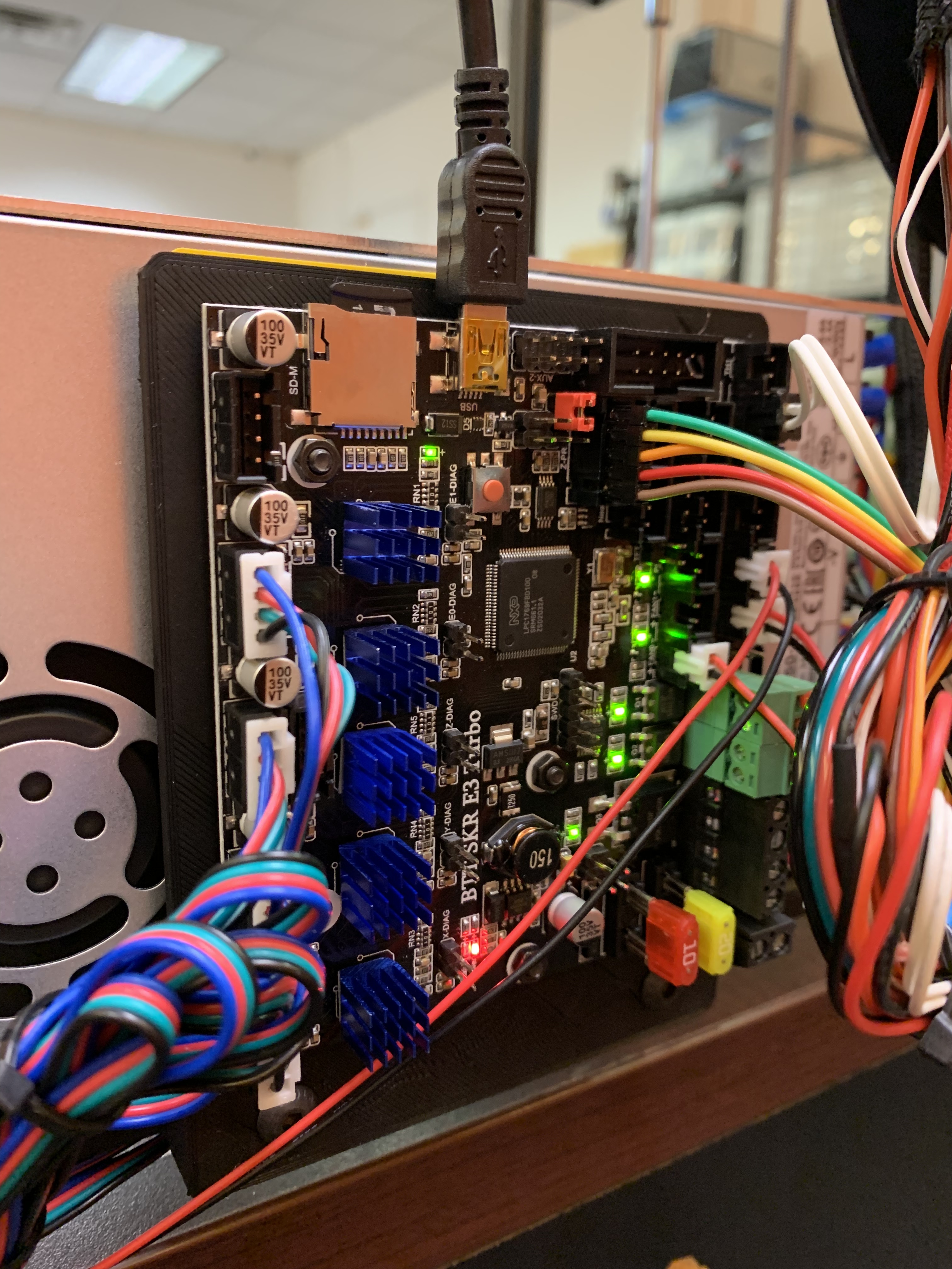
I haven’t been able to find an SKR v1.4 to replace the one I fried. So I am trying the SKR E3 Turbo now, which is functionally equivalent. So far so good.
1 Like
Thanks for the config Stewart! I hope to finish the printer in a couple of weeks. You have done a great job, I am very impressed. Self-assembly of the printer expands horizons. Now I am dealing with setting up Raspberry. I put the Fluidd system, the Clipper is installed in it. It’s just a novelty for me. https://github.com/cadriel/fluidd/releases
Stewart! I started working on the config you sent. The SKR 2 board is indicated there, and below are the TMC2208 drivers.
I tried the SKR 2 and had trouble. I ended up using the SKR E3 Turbo, which was a great replacement for the SKR 1.3 and 1.4 with drivers integrated onto the board.
Understood thanks! In this case, please tell me, for SKR 1.4 in this config I only need to replace the board from SKR 2 to SKR 1.4 and below the driver from TMC 2208 to 2209. Maybe there are some features that I don’t expect?
The SKR boards are usually sold with 2209 drivers. But you can use almost any type of driver, if you want. The E3 Turbo has drivers soldered onto the board, so you don’t need to worry about (or have a choice in) the driver.
Hello!
I am finishing the firmware for my SKR 1.4 and TMC 2209. I took your config as a basis printer.cfg
- Why did you connect
[heater_fan extruder]
pin: P2.4
exactly in pin 2.4 when is it heater for hotend1?
It seems that according to the instructions, Pin 2.3 is provided for it - Do I need to uncomment the lines in the sections like
[extruder]
step_pin: P2.13
dir_pin: P0.11
enable_pin:! P2.12
microsteps: 16
rotation_distance: 22.50
nozzle_diameter: 0.400
filament_diameter: 1.750
heater_pin: P2.7
sensor_type: EPCOS 100K B57560G104F
sensor_pin: P0.24
#control: pid
#pid_Kp: 22.2
#pid_Ki: 1.08
#pid_Kd: 114
min_temp: 0
max_temp: 280
max_extrude_cross_section: 100
max_extrude_only_distance: 200
max_extrude_only_accel: 200
pressure_advance: 0.4
and the rest?
the second hot end heater is just a PWM’d 24V, so it is re-purposed as hot end fan control so the printer can be completely silent when not printing
leave the commented lines in place. I think when you re-run PID calibration and SAVE_CONFIG, it will be over-written.
After flashing the board, I connect it to the raspberry via usb, in config, respectively, I write the address in [mcu] and then this error
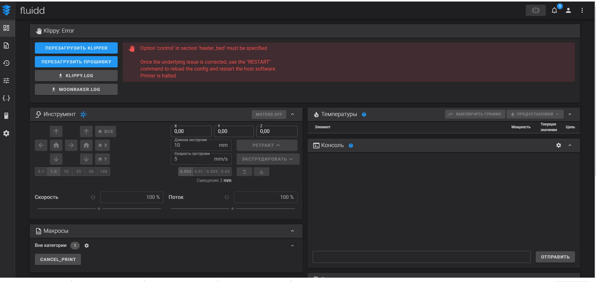
you’ll have to read up on the printer.cfg options. Klipper has relatively good docs. if you google most of these errors, it will take you to a doc page that describes the fix.
Sorry for silly question)
I’ll deal with config.
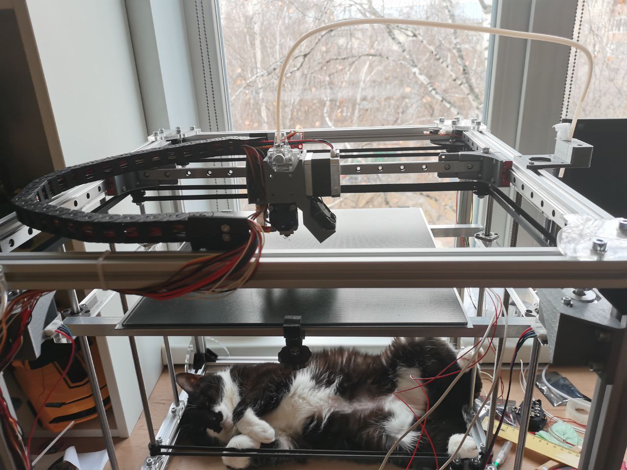
Stewart! I finally assembled the printer. Thank you very much, you are a genius! But as always there are a couple of questions))
I was worn out with the Z axis, it feels like there is not enough power to the engine. At high speeds, the table rises well, but at small speeds it can wedge. Already a hundred times disassembled, assembled, sinned for imbalance.
Have you encountered such a problem?
I already think to put the second engine on Z.
And a question on the table.
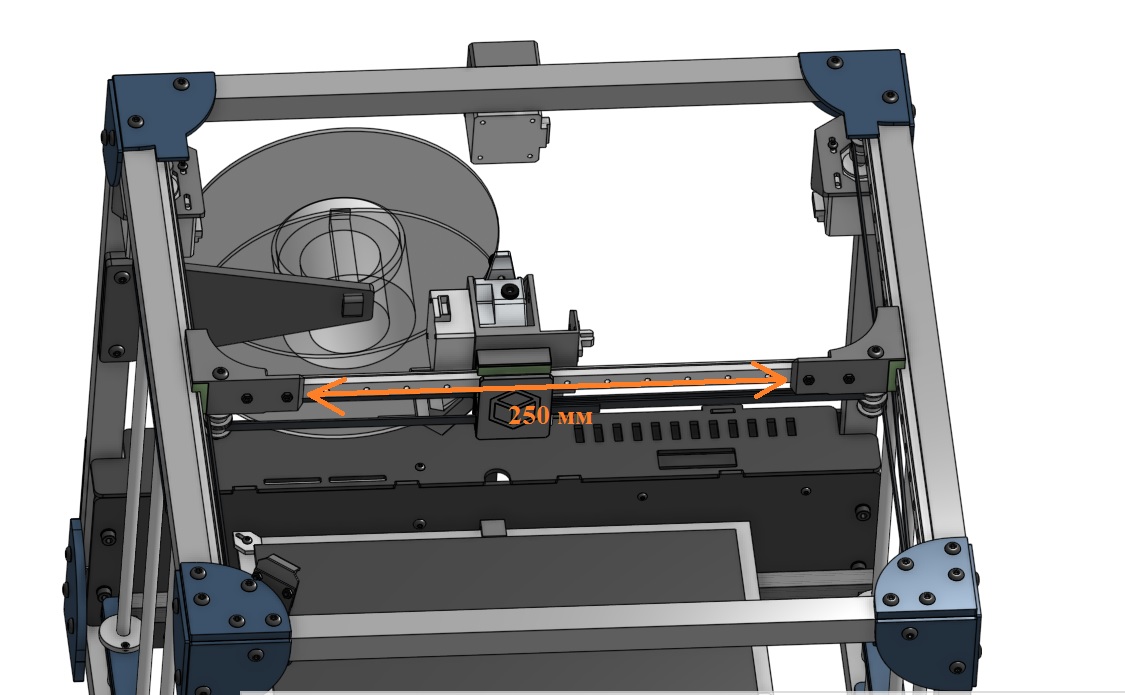
How did you achieve 330x330 space? I get 250x250. How can I achieve a larger table area?
P/S. The cat tortured me, this is her favorite place now.
1 Like
The Z axis can bind under a few conditions. First, it needs to be perfectly vertical with no skew. I printed an offset blank and used it at the front/top & bottom. Second, the lead screw guide needs to be level. If the Z axis middle part holes aren’t aligned or it’s too tight going in, this misalignment will cause binding. Third, the base of the lead screw needs to turn freely. It should not be rubbing. Most problems are caused by a lead screw out of alignment.
I can get a 300x300 build area out of bowden setups. It’s possible the direct drive eats into that space.
Everything is centered, maybe the screw itself is slightly uneven. In general, everything was decided with the help of silicone grease.
And with the X-axis, apparently I need to use a different extruder mount for the axes.
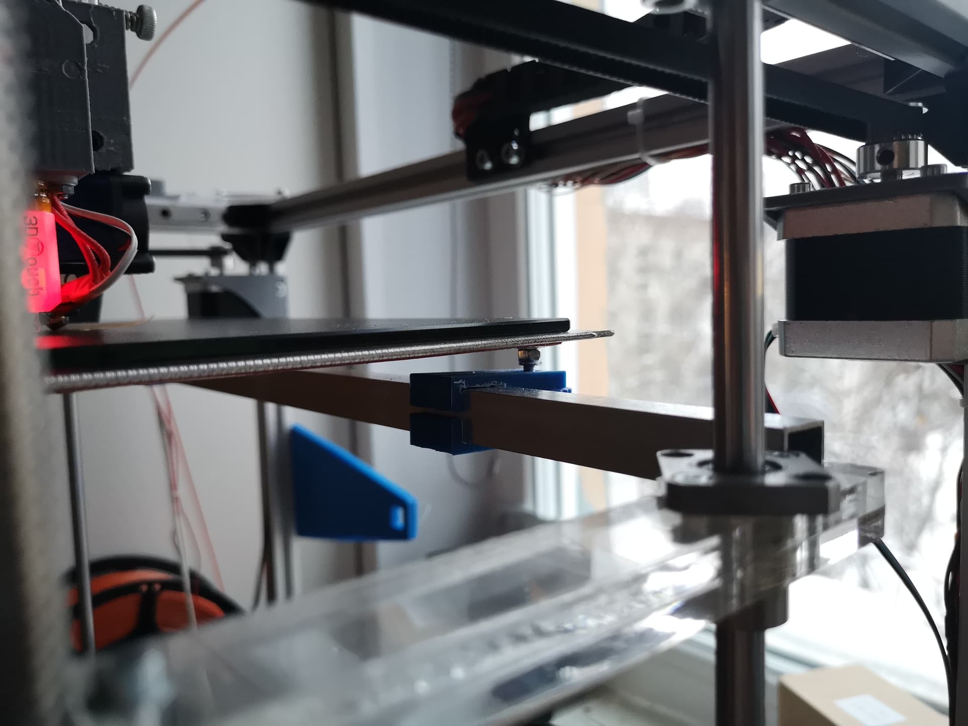
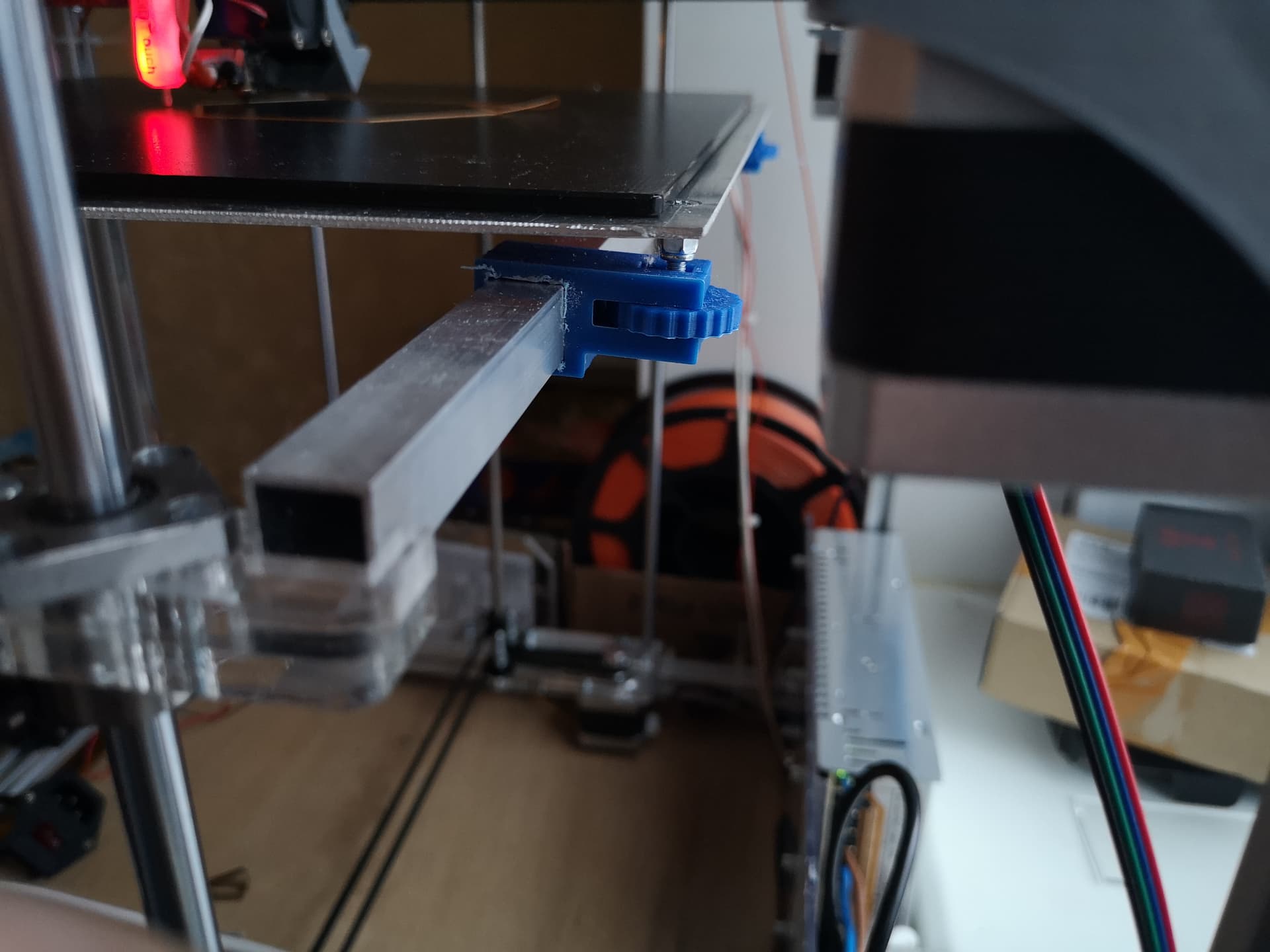
Hello colleagues. I understand that everyone has bumped into collecting GridBot 2.5, I also plan. But maybe someone will be interested. I didn’t want to come up with a bicycle and modified the table mount. Cheap and cheerful. Now the table can be adjusted very conveniently. I don’t know if it makes sense to turn off the model, draw for 10 minutes. And besides, all the sizes of the profile and the table are different.

2 Likes
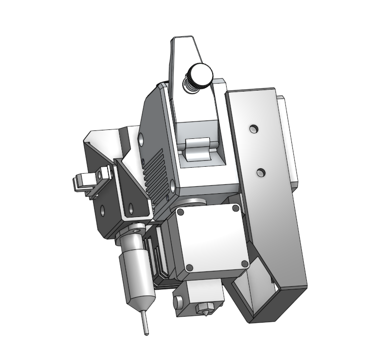
Stewart, tell me which version of the cooling case for direct did you like best for Gridbot 2? Faced the fact that this option does not work well with small details.

I did not build a dual fan direct drive variant until I made version 2.5 – I’m guessing you want it with direct drive?