Ha, that’s a good one too 
Two out of my three linear rails weren’t as smooth as I would have liked (one is great). Sending them back to Amazon. Replacements coming Thursday.
When I test-mounted them, I noticed the x rail didn’t exactly fit in the x rail mounts. The cutouts seemed to be a millimeter too short. So I might have had some issues with the dimensions on that print. So I can use the time until I get the new rails to get those parts right.
that’s annoying. same link from the BOM? I’ve ordered probably 20 of those and not had a bad one yet.
Yes, the ones from the BOM.
One runs amazingly smooth. One is not great but ok and one is unacceptable. Seems to be the rail. The block from the bad one runs fine on another rail.
I haven’t used linear rails before. But mine all moved smooth on their own and then tightened up when I mounted them. So I carefully loosened and tightened each screw, with the alignment guides Stewart had me print and I got them working better. But I eventually put some oil on them and that made them smooth out the rest of the way. Either that, or I drove them enough times that they worked themselves out :). I am sure yours are bad though, if they act differently out of the box. Good for you sending them back.
New rails came early. They seem to run fine. Put some super lube oil one (thought about using the super lube grease - some people recommend that - but i went with the oil) and installed them during my lunch break. At first they were binding up when i ran the x all the way to the front, but then I found that one of the corners of the frame had an every so slight gap between two extrusions. I loosened that corner and the rails started running smoothly. I I’ll re-tighten the frame later and make sure it’s square (I thought I did that the first time, but I must have missed something)
Anyway, things are back on track it seems 
Getting a square frame and perfectly aligned rails are always harder than you imagine. The slightest misalignment can cause binding. Same with the Z. But once it’s dialed in, all smooth.
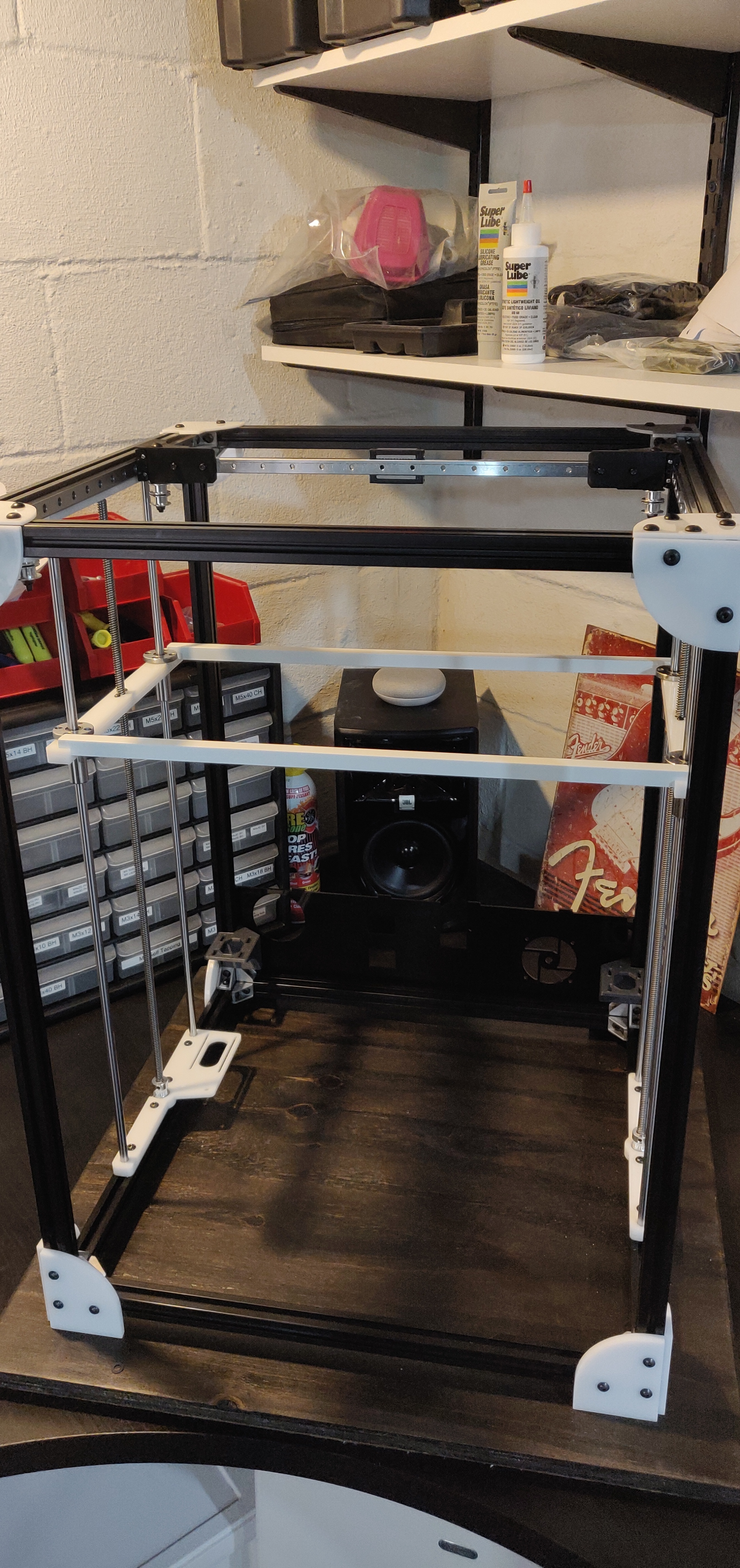
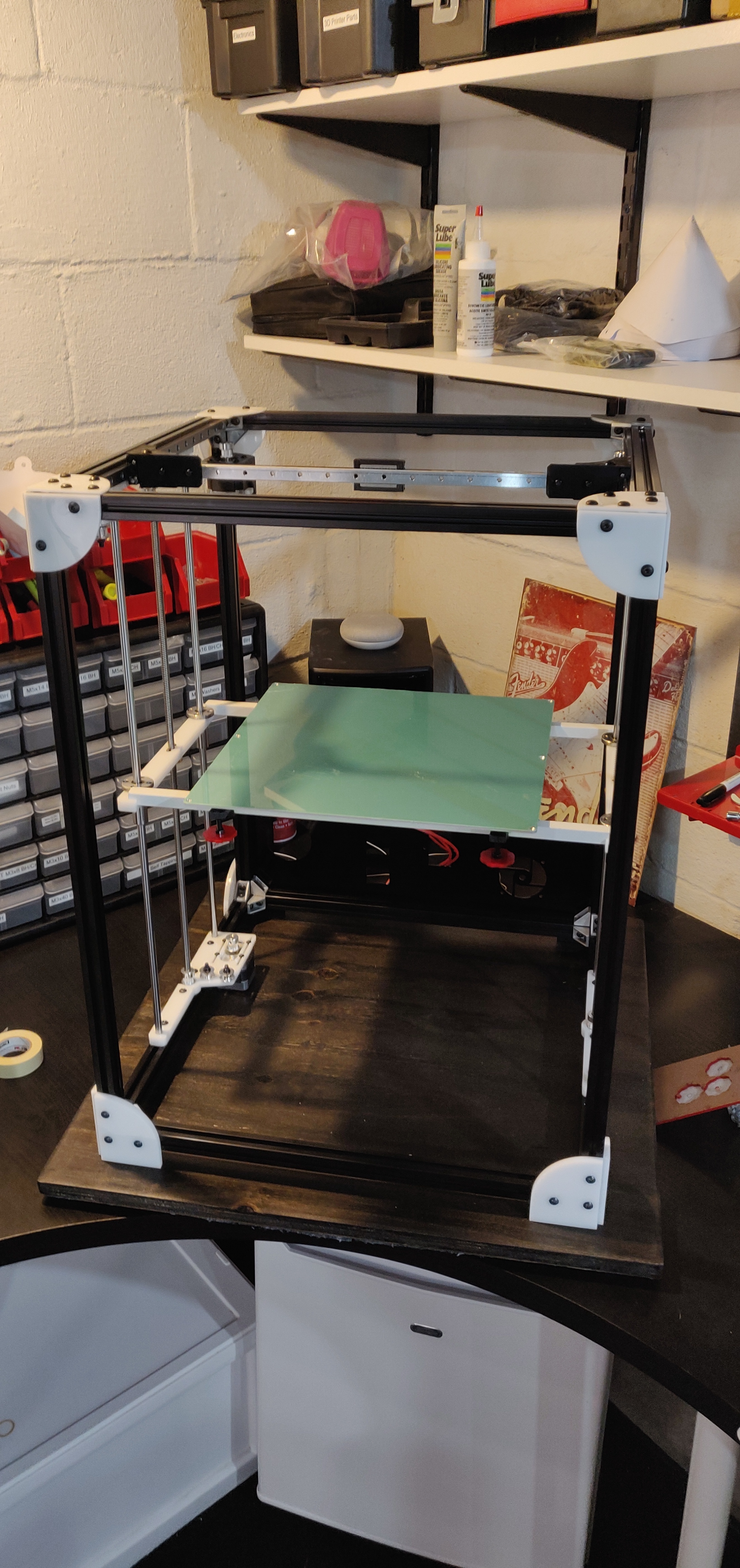
All three axes seems to be in good shape now. Added all the idlers, pulleys and motors and was just working on the bed support.
How exactly do you attach the bed to the carriage? The CAD shows bed clips, but I’m not quite sure what to make of them. The photos I saw don’t seem to have any clips.
Any suggestions?
I’ve done this three different ways:
- cork sitting directly on level bolts
- cork sitting directly on level bolts with SLA printed caps
- heated bed sitting on level bolts with clips
In all three cases, the bed is floating so that does not become over-constrained during heating / cooling.
Thanks, @stewart . Since I also have a 330x330 bed, I think the best option would really be to juts sit in on top of the leveling screws. My bed has a cotton/aluminum insulation backing that I was going to keep. Not the best for the point of contact. So maybe I’ll just replace the parts with cork that will make contact with the leveling screws. And make sure I won’t yank the bed off every time I take the spring steel off the magnetic base
I also need some kind of strain relief for the bed wiring.
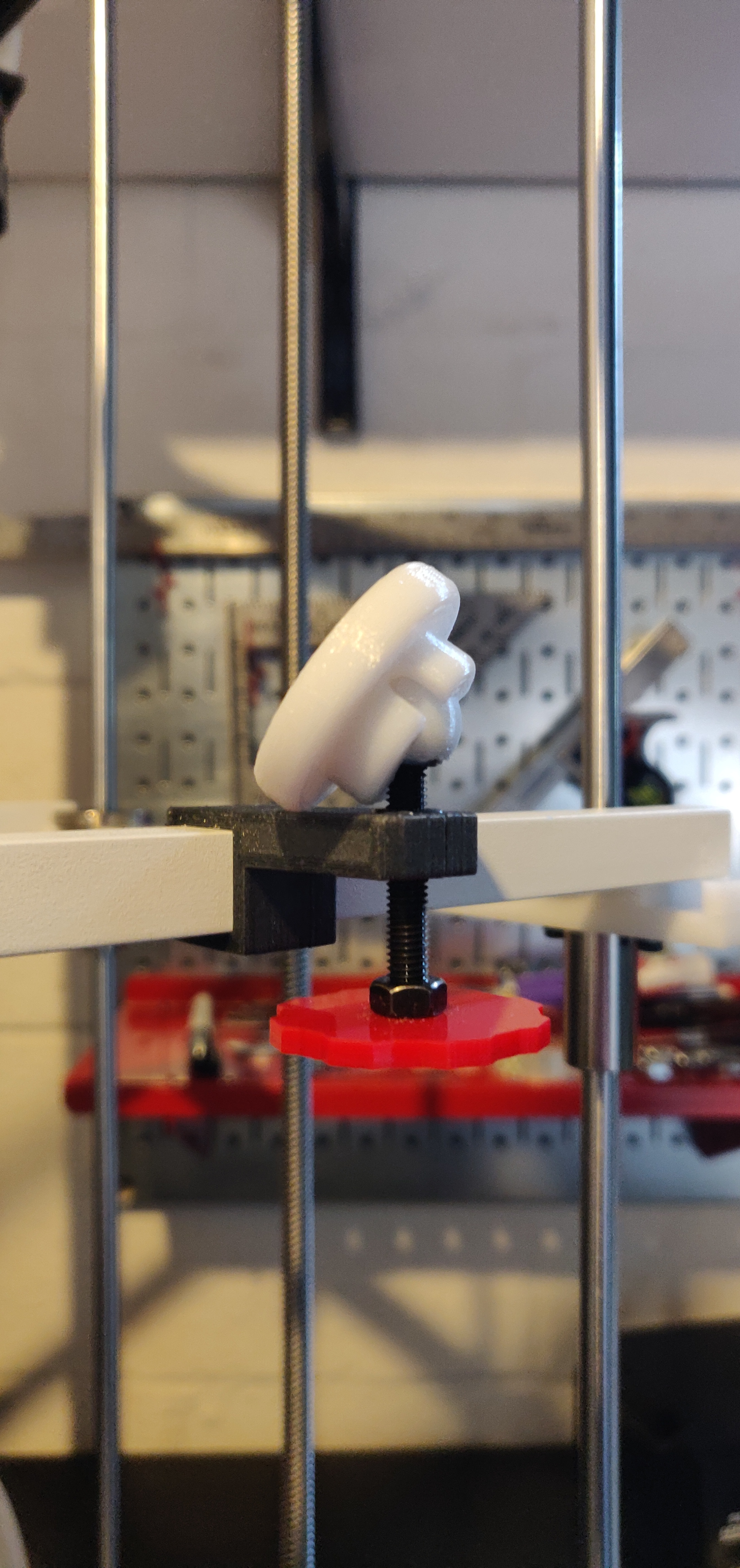
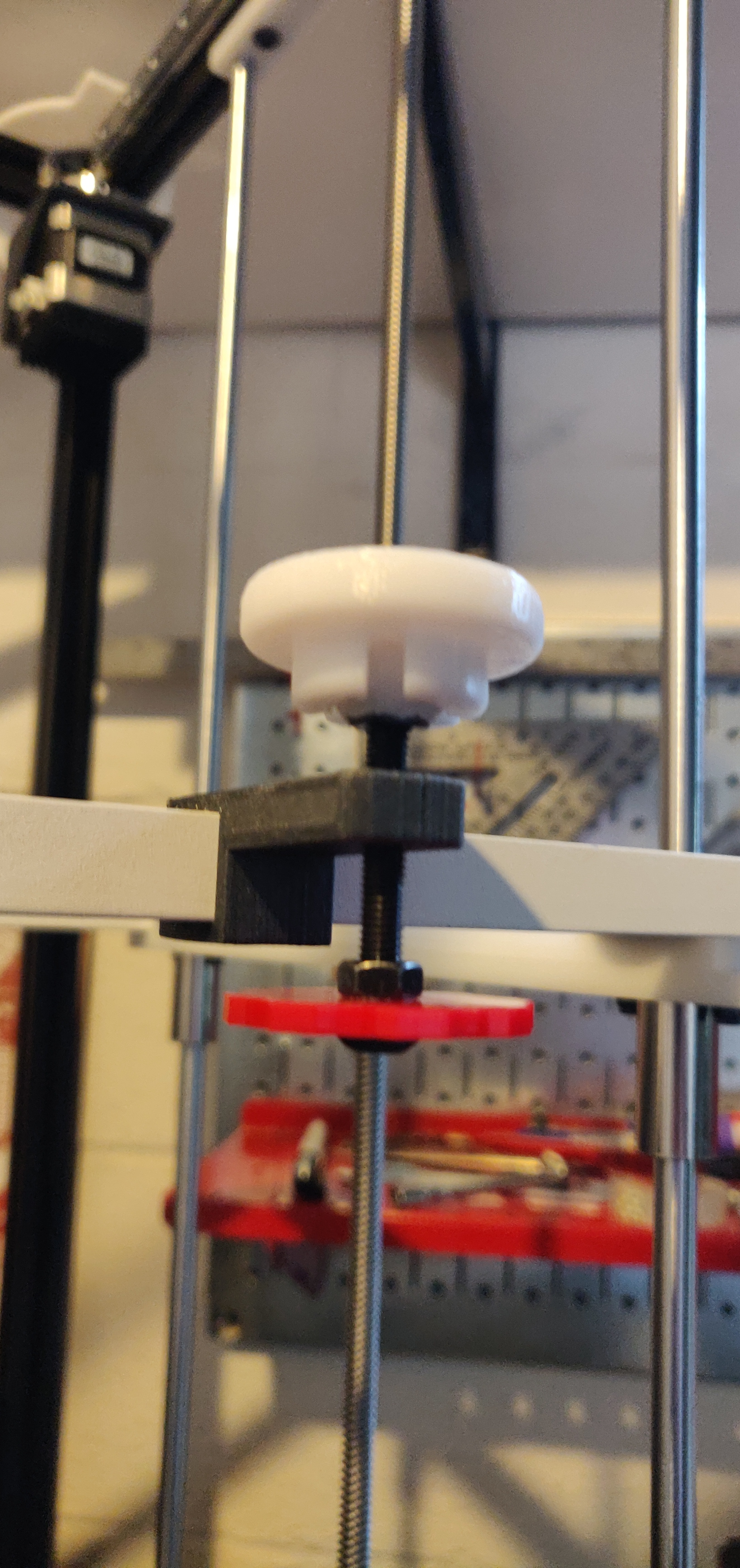
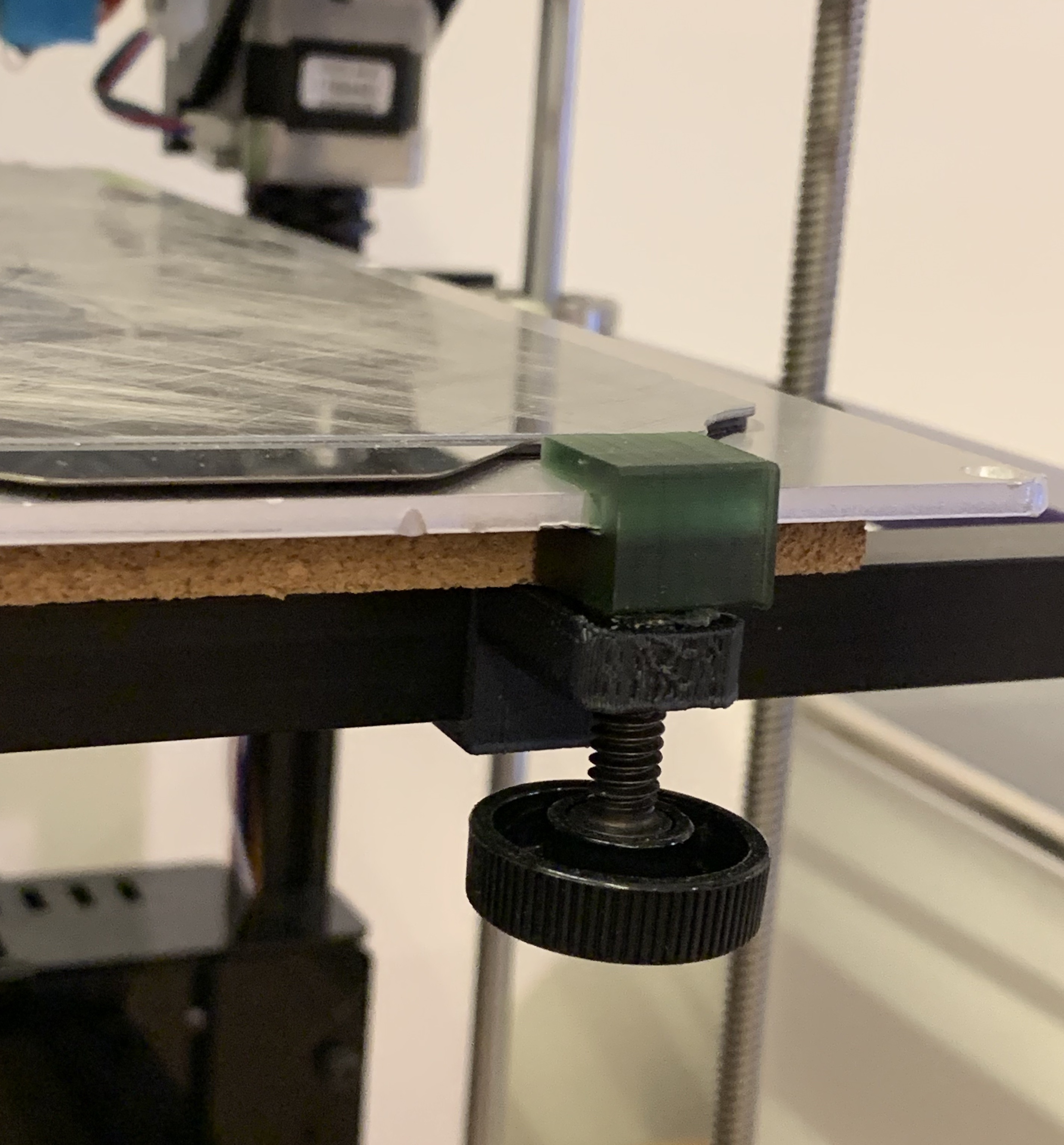
I built a little prototype of something that might work for me. I printed this in PTEG. The joint could be attached to the bed with 3M 468MP tape. The ball sits loosely in the joint and allows the bed to move as it gets hot and the screw to turn when I adjust it. But it will still hold the bed in place when I remove the spring steel build surface.
Interesting. I like that a lot.
I’ll tweak the bed level model a bit more and then I’ll post an update here.
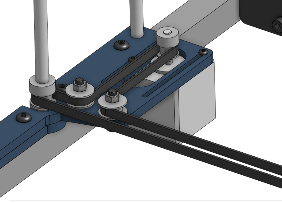
I have a question about the idlers.
TL;DR Too much force on idler assemblies seems to inhibit otherwise smoothly turning idlers from turning freely. This happens either from (1) tightening the lock nut all the way to prevent the assembly to “tilt” under belt tension or (2) from the belt tension if nut not tightened all the way, so the belt would slightly pull on and tilt the screw. Washers don’t seem to help in case (1) since the standard OD is wider than the width of the bearings of the idlers, so they still push against the idler wheel.
Long version:
I saw on @jeffeb3’s thread that there were issues with idlers not turning smoothly under tension. How was this solved eventually? I haven’t put a belt on yet, but I can already see that all the idlers run fine without tension, but if I apply some tension or pressure, they don’t seem to be turning very well any more.
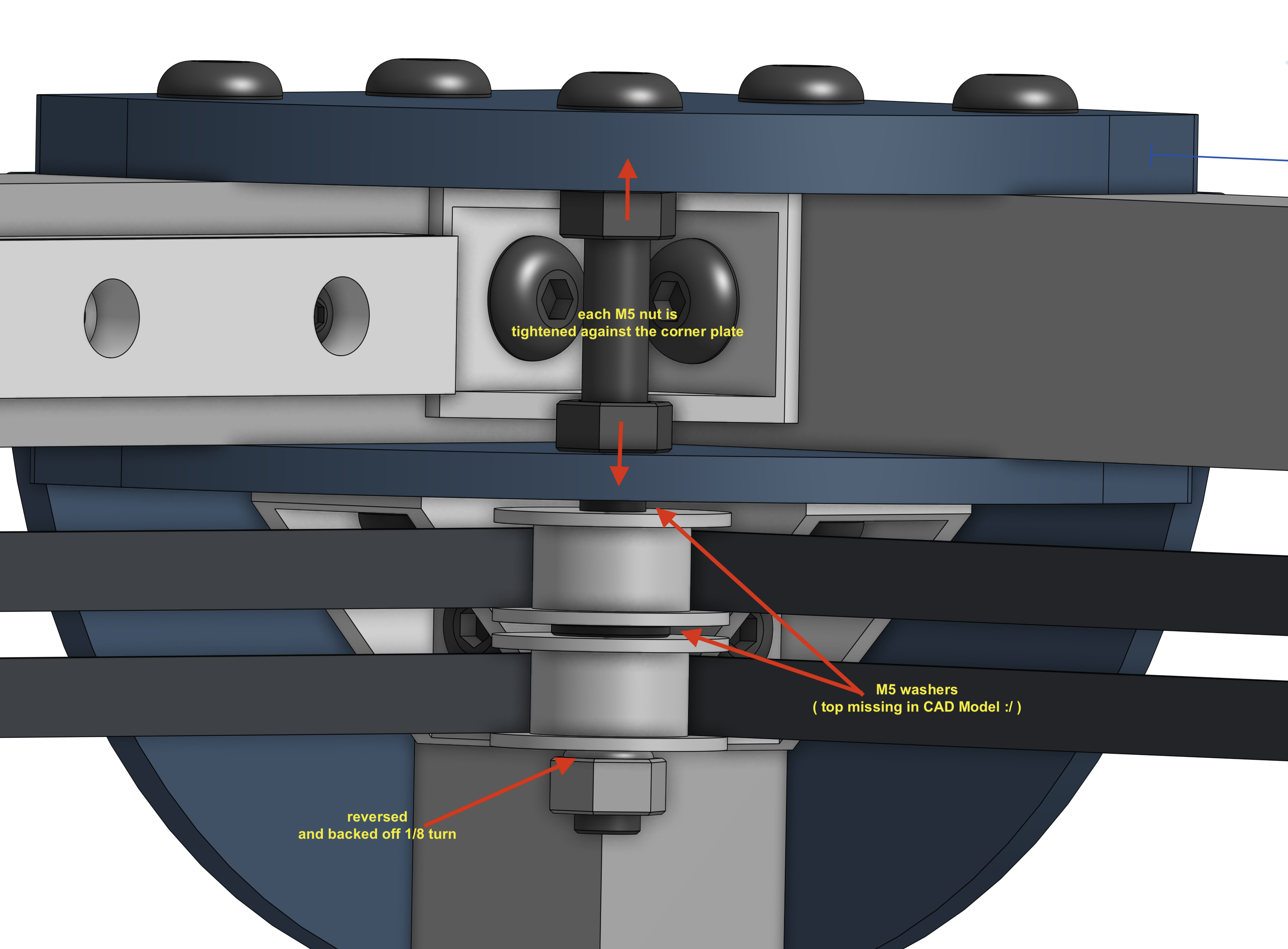
On the bottom idlers, for example, I use a reversed lock nut on top and then have an M5 metal washer between idler and the acrylic base. If I don’t tighten it all the way, it runs smooth without any tension. If I push a bit against the screw to simulate tension, the idler won’t turn well any more. Probably because the screw isn’t 100% locked in place since I didn’t tighten the nut all the way to allow the idler to turn.
If I do tighten the nut all the way to stabilize the screw, the idler won’t turn. Probably because it’s being pushed against the bottom washer which has a 10mm OD and is therefore wider than the bearing and touches the idler wheel.It might work with a 8mm OD to allow both the nut to be tightened and the idler still to turn. But I don’t know if there is such a thing for M5.
Since I don’t have the belts on, I don’t know if this will be an issue or if the belt tension will not affect the idlers too much. But now it’s still easy to change things …
I am trying to remember. I made the long screws tight to the plates that they attach to, but the lock nuts on the bottom of the idlers is backed off 1/4 turn.
That’s basically what I’m doing right now.
I just found some M5 washers with 8mm OD. I’ll see if those would allow me to tighten things a bit more without binding up the idlers.
But looking at the bearings more closely, I don’t think it’s going to make a difference.
So, while the l long bolts on the top have a counter nit to fasten them to the acrylic, the bottom ones only have a single nut pushing against the idler. I think that’s the ones I’m mostly concerned about. And adding a counter nut to tighten the screw against the acrylic there would lift the idler up too much, so that’s a no go.
I’m less concerned with the corner ones, because here we have additional nuts to fasten the bolt. Also the ones on the x axis are fine, because the bolt grabs very well onto to the x-assembly.
I’m more concerned with the ones by the y stepper, because here the only thing holding the bolt in place is the nut pushing against the idler. But maybe I just need to find the sweet spot of tightness of the lock nut against the idler so that the bolt is stable but the idler still turns ok. That might be sufficient. As I said, I don’t have the belts on yet, so this is purely a simulation for now.