Hi all,
I thought I’d start a new thread as I’m in the process of sourcing the materials for a GridBot v2 build.
I already commented a bit on openbuilds, but I thought continuing here is more appropriate.
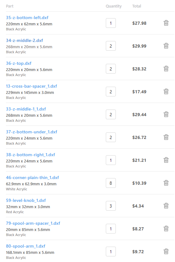
As I had mentioned on openbuilds, I do not have access to a laser cutter but still prefer to have the relevant components cut rather than printing them. I just exported the DXFs for all pieces and I’m planning on having them cut at ponoko.com.
They asks for a 0.2mm kerf for acrylic, so I set this value as the offset in the output settings in kiri:moto.
Ponoko does not have a 6mm option - only 5.6mm and 9mm.
Looking at the CAD model, I don’t think 5.6mm should be an issue. What do you think?
1 Like
Welcome Oliver! 5.6mm should work out fine for the thicker pieces. Do they have a 3mm option for the thinner ones? The only place this tolerance might matter is the lower idler plate under the front/top corners. You would also want 3mm for the electronics enclosure.
@jeffeb3 what do you think? I know you 3D printed all your parts.
Oh yes, they do have 3mm.
I was only referring to the 6mm that would have to be replaced with 5.6 or 9
I did all the 3mm pieces as 3mm
1 Like
I 3D printed almost all of the flat parts. They seem more than tough enough. I couldn’t fit the enclosure on my printer, so I cut that from plywood. Same with the two carriages that hold the Z leadscrews (I’m AFK, I don’t know the name).
I don’t think 5.6mm would be a problem for any of the 6mm parts. It may be an issue for the 3mm parts. But it might also just be a a longer screw in those corners.
The enclosure has interlocking parts, so that definitely needs to be changed or the right thickness needs to be found.
Here’s what I was thinking. A black and white acrylic 3mm/5.6mm
The enclosure is all 3mm and it seems Ponoko stocks that.
Ok, sounds like this would work then. I appreciate the input. Maybe I will print one of the smaller parts to see if I like the result and maybe go with printing instead of the laser cuts since @jeffeb3 seems to have had great results with that.
I can’t remember every setting I chose for these parts, but I centered around 60% infill, 0.2mm layers, 3 perimeters and 6 solid top/bottom layers.
Unless you’re pretty confident in your printer, it would be good to print a few tests pieces to make sure your printer is square in all three dimensions.
My flat parts are very nearly as stiff as an acrylic part would be, and either way, they are much tougher than they need to be. So you should have some room to find something that works.
1 Like
Thanks @jeffeb3
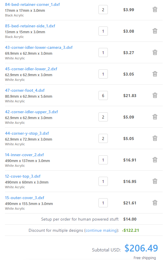
I decided to go with the acrylic after all. Just submitted my order. I didn’t pay for rush production, so it’ll be about four weeks until I get the 43 acrylic pieces, but I’m not in a rush.
I went with all white pieces except for the enclosure covers (black). That’s probably similar to @stewart’s white GridBot.
1 Like
I’m thinking about doing a 450x450x650 build.
I assume the shaft rods and lead screws would be 600mm then.
I was also thinking to get a T8-2 lead screw 1 start instead of a T8-8 with 4 starts. Probably doesn’t matter much. Pitch still remains at 2mm
Does anybody see a reason not to go up to 650mm height?
My white GridBot uses 550mm extrusion for the Z. I see no reason 650mm wouldn’t work just as well.
Excellent, I didn’t think there’d be a problem with that either. So I’ll go ahead and do that.
I ordered 450 and 650 extrusions from Misumi and 600mm rods on Amazon
You may have to slow down your Z with a 1 start. It needs to spin 4x faster to reach the same speeds. It may not matter with a 24V power supply though.
Yes, you are right. I think that should be fine.
I just found a 4 start in 600mm and went back and forth whether I should get that instead. Based on what I read a lower lead should be an advantage despite the fact that homing would be slow. But in practice it will probably not really matter. I’ll try the lower lead after all…I can still switch to a 4 start again if necessary
Has anybody considered a 1 start? Does it make a difference? E.g. in terms of backlash movement?
Where to you think I would need to adjust speeds?
I see this question a lot as it relates to the MPCNC, where I spend most of my time helping people. So this is sort of from that perspective, where things are heavier and Z movements are larger, as you plunge into material.
Regarding backlash, as long as the bed is free to move, there should be basically none. The bed is heavy enough, and the plastic/nozzle is pushing down, not pulling up, so it should always stay at the lowest spot regarding backlash.
For the same torque on the screw, the 1 start should have 4x the force pushing or pulling. But it will move 4x slower for the same motor shaft speed.
If you try to move the bed at 15mm/s with a 4 start, the motor shaft is moving 4x slower than 15mm/s with a 1 start.
Stepper motors have the most torque when they are moving slower, so as you go faster, they will have less torque. If the friction and the weight of the bed are greater than the torque, it will skip steps. I think that is a 10x bigger issue in CNC than in 3D printing. Most of the Z moves in 3D printing are so small, there isn’t any speed that would matter, except when homing.
A 24V supply doesn’t give you any more torque at lower speeds, but it does increase the speed where you really lose torque. So it is probably not a huge deal.
You can set the homing speed slower in the Marlin configuration. You can also just set the max Z feedrate with a Gcode (M204, I think?). It can also be set in the slicer.
3 Likes
Thanks for that summary. That makes a lot of sense. I just saw that I hadn’t actually ordered the screw yesterday, so given all of your insight I’ll just stick with the 4 start and that’s that. But now I have a better understanding of the differences. I had never given this much thought before.
I’ve ordered more than half of the components in the BOM. Spent a good part of the evening trying to find a suitable heated bed, but haven’t decided yet. The one @stewart mentioned in @jeffeb3 thread are either unavailable or not available before mid/end September. I did see a few others, but the sources made me question their quality.
Also saw that e3d makes a mains-powered bed. Supposed to reach 100C in 80s. But that’s overkill - and not cheap 
Oh well, I’m not in a rush. I’ll keep looking.
I guess I should also get started printing the printable components on the BOM soon.
I was never able to find a reliable suppliers of heated beds
Have you ever considered a silicone heater mat instead of a PCB?
I have only used PCBs so far, but it looks like the silicone mats are more readily available in arbitrary sizes and also seem to be less likely to cause build plate bulging.