Thoughts on Duet Boards for future expansion

everything should be in the CAD models. maybe share a picture of what you’re looking for.

Sorry Stewart, was your reply aimed at at me? :pleading_face:

yes, in response to your request to share the X axis mount design. if it’s not in the beta cad doc, if should be in the 2.0 design. can you share a pic if i’m missing something?

Ah ok, sorry I’m a bit slow :slight_smile:
I was actually referring to @sigfrieds design, I might have been unclear about that.

BTW, is the 2.5beta still the latest one of your magnificent work?

ohhh. yeah 2.5 is the latest thing I’ve published. I’m building out a new lab and hope to re-start publishing updated designs before summer.

1 Like

Howdy again, just now coming back to this having finally assembled and tested this. I’m not currently hosting the files anywhere, but I’d be happy share more details if you’d still like them. I still need to tweak the design to use the optical endstops stewart suggested. While it’s not really a Grid bot anymore, I tell anyone that asks how great of a place the gridbot is to start.

2 Likes
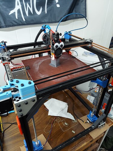
love the mods. i have an orbiter on one, too. is the z using three steppers?

Yes please🙂
Are the metal parts custom made?
How come you went with stepper mounts outside the frame like that?

I feel like my 4 yo daughter, why why why why😁
Feel free to share more pics as well!

The orbiter is fantastic, definitely one of the better purchases I’ve made for the printer. The three z steppers is a concession to my minor obsessions’ with the HeVORT project, and hope that non-planar/5 axis slicing will become more mainstream, though all it’s giving me right now is some serious z-banding :grimacing:

As far as the metal parts go, I had them laser cut by Send Cut Send. I’m honestly very happy with the results, I was barely over the minimum order of $30 for the motor mounts and x axis mounts cutting out of 3.2mm 6061. I’ll probably be slowly replacing other printer parts with laser cut metal ones, especially motor mounts/things exposed to heat.


I put the xy steppers outside the frame for pure geometric reasons, as I couldn’t clear the potential enclosure cover with internal steppers without reducing print volume. It will have the side benefit of keeping the motor outside the enclosure once I build that, but realistically that’s pretty minor.

If you’re interested in the details of the motion system, I tossed it into an Onshape document. Onshape

Thank you so much! I didn’t get a notice that you had replied, that’s why I was so slow to answer.
I’ll have to see if there are any cheap cutting services in the EU, I love the metal parts. One problem however, is that I feel I’m not really done customizing the printer, I’m still finding new stuff I wanna try out :slight_smile: It feel a bit unnecessary to order metal parts until I’m really sure(don’t have a lot of money for things like that).

Big thanks for the Onshape!
I tried EVA 3d on my printer as well. I really like it, but I had problems with movement system and I lost some bed size. I would like to go back to it, but I need to solve everything else first… I made a custom version since I’m using a modified “Superfly” extruder. (Superfly Extruder - A Compact BMG Conversion by mustcode - Thingiverse)

I’ve started thinking about a belt driven z axis, geared probably, but it’s only a thought so far.

Edit: are you still using a Duet board? I’ve really tried to like the Duet 2 WIFI I have, but it’s so noisy…

I used printed version of most of these parts before I ordered them, so I was pretty confident it was what I wanted. All of these accept the motor mounts worked pretty well in PLA+.

I pretty much ground up made this motion system for the EVA, the belt spacing is a little wonky so it wasn’t a great direct gridbot conversion. Belt Z has never really appealed to me, but it’s starting to grow on me with the amount of trouble I’m having getting rid of artifacts caused by slightly misaligned lead screws.

Yep, still using the duet board. The Duet 3 boards have stealth chop, and I really like the way RepRap firmware works with Duet Web Control, even above klipper.

Yes I thought as much.

I’ve used PLA+ as my go-to “try out new parts” filament as well, with some petg mixed in here and there.
What got me convinced of the belted z axis is that after a year of trying so many different things on my Ender 3v2, I converted to belted z and it made all the difference. I’m not having any real problems with my Gridbot, but I’m not fond of the lead screws inherited flaws.

Ah ofc, stelthchop makes a big difference.
Thanks!

Interesting read on belted Z – I’ve never noticed problems with Z screw drive in any of my builds. Is it possibly a manufacturing issue?

More than likely I suspect, running $10 screws myself. I’m not sure if temperature plays any roll though.
I really like the smooth and almost fluid motion with the belted drive though and you never have to think about lubrication or dirt/contamination. The only potential problem might be that the bed can drop when powering off, that’s why I’m thinking geared belted drive might do the trick.

Edit: geared or a belted pulley system of sorts.
Edit2: or use a magnetic brake like the ones used on mobility scooter motors (I have 2 of them that’s how I know :slight_smile: ) The magnet engages on the axel when the motor stops or when the power goes off.

How’s the printer doing, are you happy with the motion system?
Also, the bed mounts, are the your design?

Going strong, still working out some z banding issues that are caused by the 3 point leveling mounts. The motion system is phenomenal, I’m running 180mm/s 5k accel with no major ghosting, and I haven’t messed around with any input shaping yet. If I were going to make any changes, it’d be to a fully single piece cnc’d aluminum plate to mount all the rails and motion components to, for maximum rigidity. But that can wait until my CNC build is done.

The bed mounts are my design, but are heavily inspired by the kinematic mounts found on the ratrig. I wanted to avoid using the internally threaded ball bear specc’d on that printer, as getting one shipped to the US would have been nearly $40 each for a 12mm ball bearing. I’m just using standard 12mm bearings super glued into mounts on the bed, and the natural weight holds them in place.


This is a generation old, but it still functions much the same way. You have three mounts, each constraining motion in 2 directions, so you end up with control over height, x-tilt, and y tilt. Pretty limited angles at the moment, but that’s an easy improvement if I actually need it.

2 Likes

Wow, that is impressive!
If you continue to improve on your design, I would be very interested in seeing it🙂
Thanks for responding!

If you don’t mind, what kind of endstop are you using on the x-axis?
I’m having a bit of trouble with the amount of play on the idler pullies, might print some shims.

I realize that you didn’t share your design with the intention that others would build it, but I did. I’m having problems with resonance in the belts, no matter how I position the pullies. Is this anything you recognize from when you built yours?

Edit: had bad idlers, working now.

1 Like

My x endstop is still sensorless homing, which is less than ideal. This is mostly because I haven’t put in the time to figure out how to wire a fixed end stop for x that triggers reliably without mounting it either on the hotend or gantry. I’ve found sensorless homing to be less of an issue when the entire mass of the gantry isn’t moving, but I’d still like to move away from it.

Also, I’d love to hear feedback on the design if you’ve got any. I didn’t really expect anyone else to build one, but I’m certainly curious how it turned out.