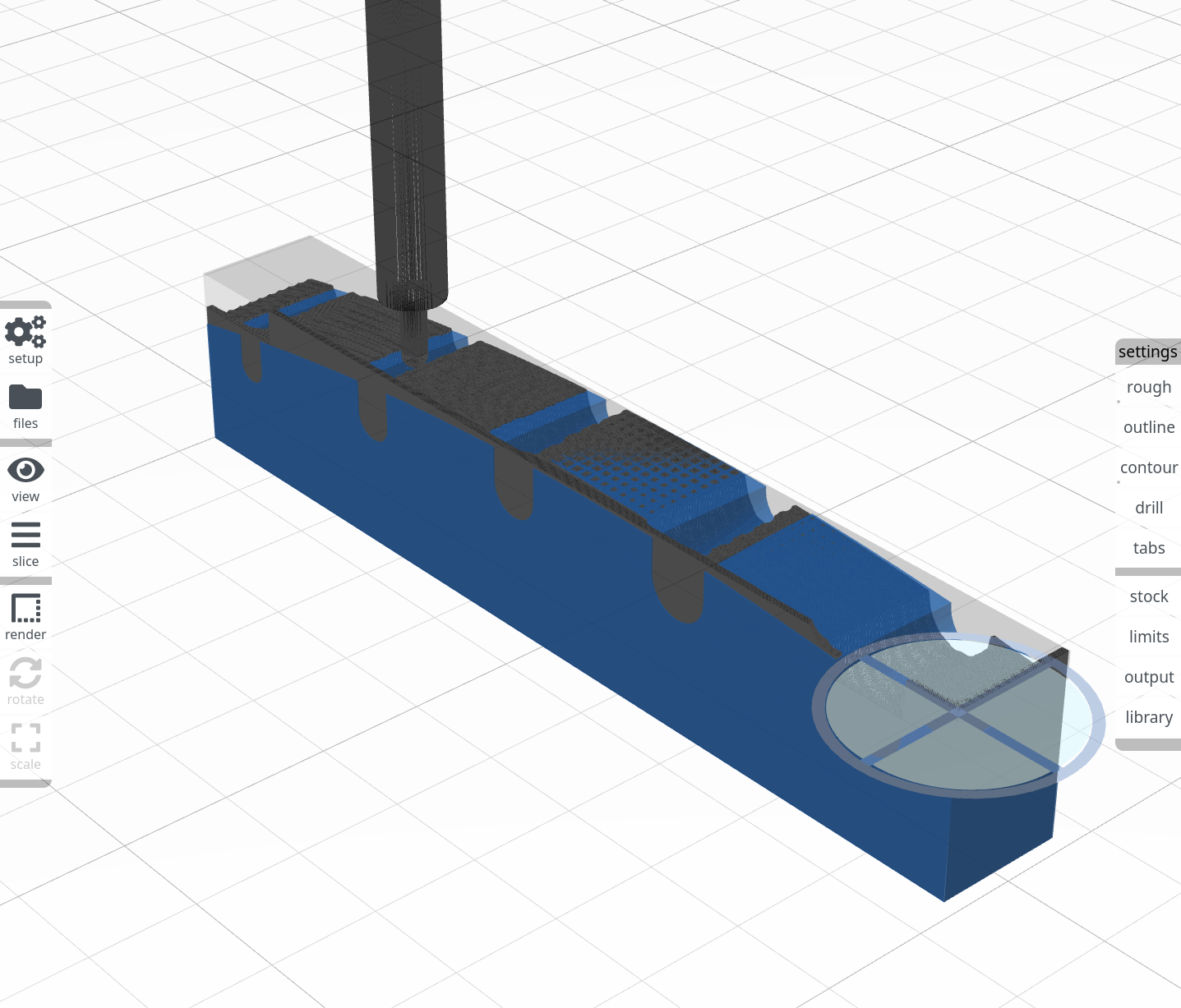
Unfortunately it didn’t work out perfectly, as you can see in the screen grab, but I think that could be related to the small scale of this part. The mill used for surfacing is just 3/64". Anyway, aside from what appears to be an offset issue, the animation was very cool to see! Unfortunately, my rather old CPU meant the animation itself was rather slow – probably close to real time instead of sped up, even though I clicked the speed-up button several times. If I switched to a different browser tab it ran much faster in the background.
@jsiddall if you make the tolerance value smaller, does it help with surface accuracy? for small parts or fine features, it needs to be proportionally smaller. also, make the stock larger (offset a bit) and try a finer mesh (400, 500?) under preferences
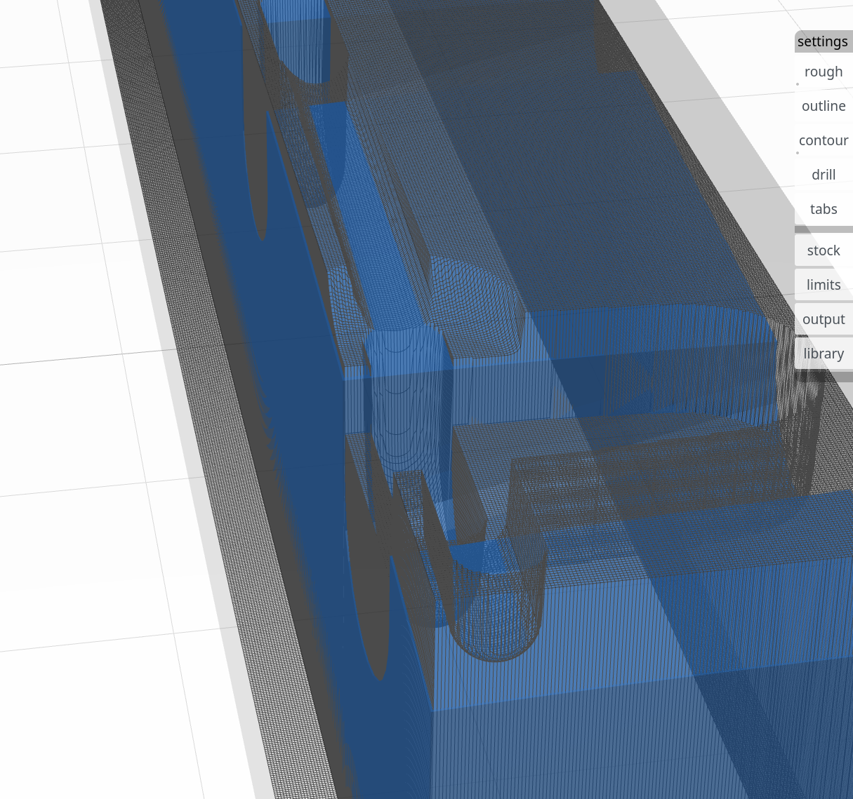
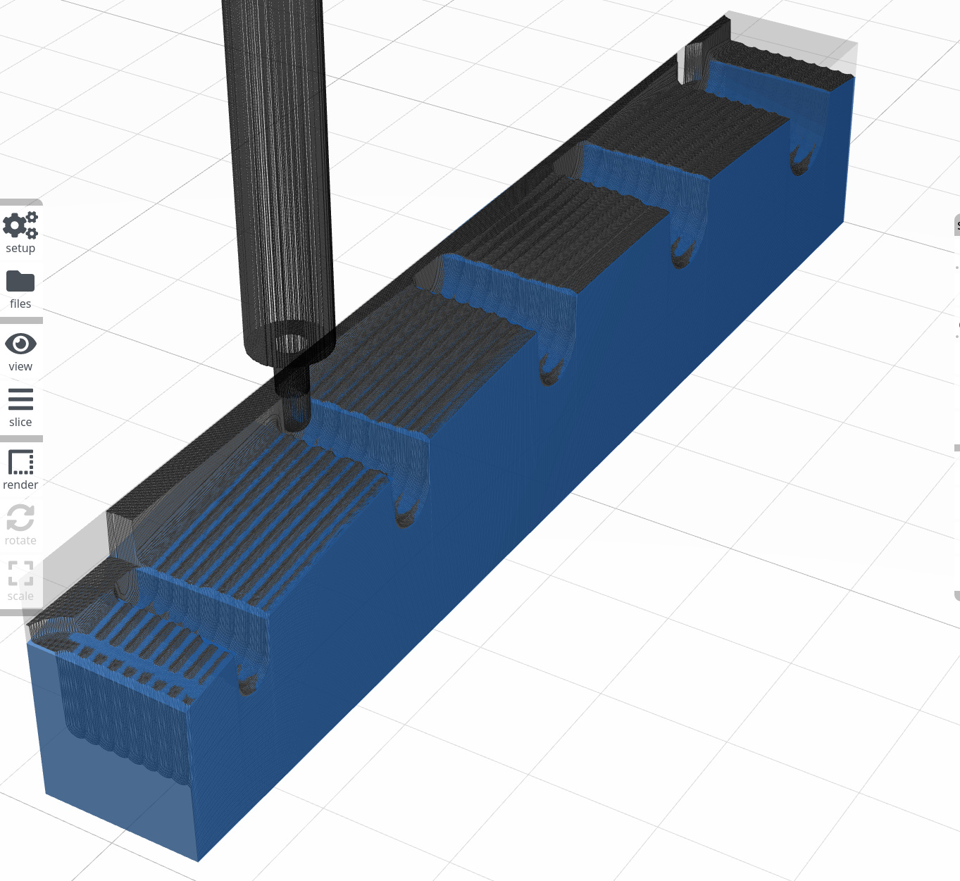
I zoomed this one in a bit more so you can see, especially on the slots, how the surface is not aligned with the model. Interestingly, it seems the offset is only on the surfacing pass. You can see the roughing on the widest slot (where a 1/8" end mill would fit) is exactly where it should be.
@pgf thanks for the tip on the speedup. I tried counting my clicks carefully, but it really made no difference. The issue is almost certainly the browser. It’s at 100% on one CPU, with 15 others idle.
@stewart I added a 2 mm offset on all 3 axes but unfortunately, only one surfacing pass in, it’s clear that didn’t solve it:
I installed the latest master and noticed the nice new indicator for the render speed.
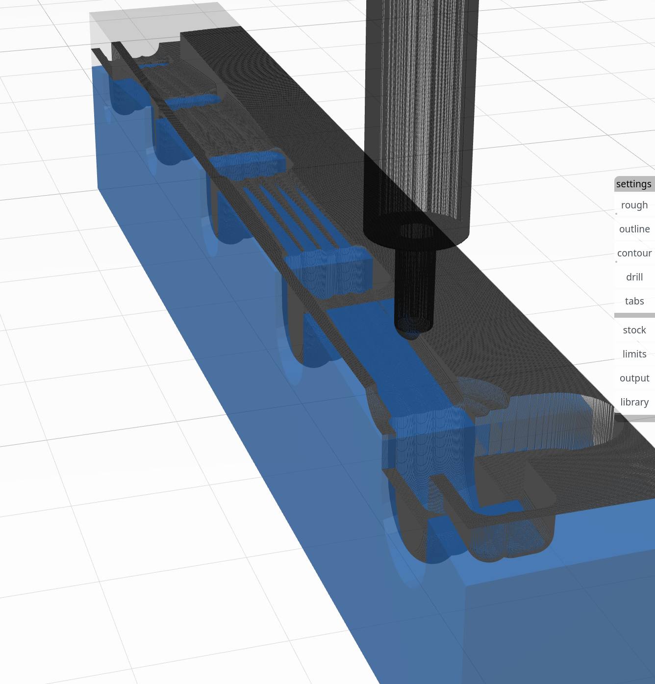
The animation is definitely better, though still not perfect. One very strange thing is that it appears to now run the outermost pass using the bottom of the shaft as a cutting surface!?! You can see the round flat part in the bottom right corner of the piece with the flute cutout below that, plus the Z steps at each of the slots:
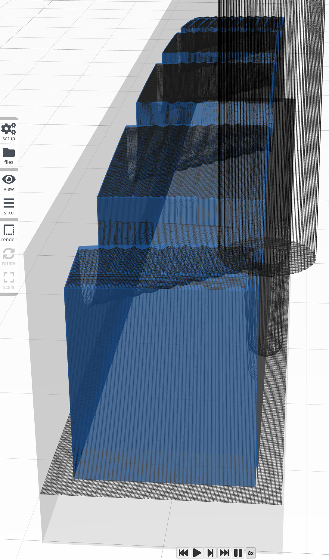
The other issue is with the offset, which might be only in the Y-axis now, and maybe then only on the “x pass” part. After the y pass finished there wasn’t much removed compared to the x. You can see the tool marks on the visible end of the piece, plus the large areas of solid blue in the bottom of the image, and large areas of solid black at the top of the image:
Unfortunately I never grabbed another screenshot after the y passes completed but could do that if you want.
One other odd thing I noticed: If stock is enabled but offset is disabled, then the stock seems to disappear (like being disabled) and preview doesn’t work. I expected that offset disabled was essentially the same as enabled with all the values set to 0. If that is the case then either allow the stock to work with offset disabled, or remove the offset checkbox altogether.
Even when stock is enabled, there is no “little dot” in the corner of the stock box to give the visual clue that it is enabled. You probably only built the little dots for milling operations, but it would be nice to have the dots on anything that can be disabled.
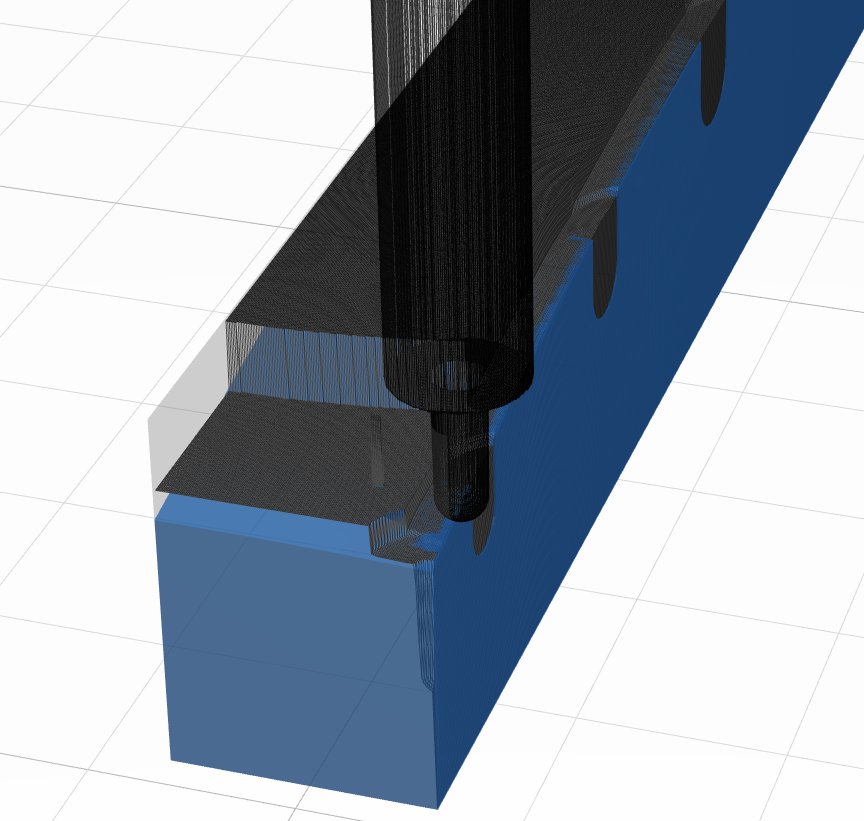
Update: I did re-run the animation again, and it looks like the y pass is also doing the “outside operations” where it runs the full length of the flute down the side. On the low X side it aligns the flutes with the edge of the part, but on the high X face it actually cuts into the part:
the preview should show these moves prior to animation (outside passes). if the tool is rendered correctly (shaft > flute diam and flute len correct) then you are seeing a tool collision in the animation that would be replicated in the actual cut.
@stewart Yeah, that makes sense. In reality there wouldn’t likely be a collision, as on a typical tool there is a taper at the transition between the flutes and the shaft, though the likelihood of a collision would depend on just how much excess material was left after the roughing pass. I guess that could be up to half the diameter of the roughing tool, so… maybe.
A future optimization could be to allow a configurable vertical cut depth so the user could set how far down the side of the part a tool would cut when the flutes are shorter than the height of the part and the shaft is a larger diameter than the flutes. By default Kiri:Moto seems to use 100% (the full flute depth).
So to summarize the x and y pass contours: both the large X and Y faces are being cut into by a good amount of the radius of the tool but the small X and Y surfaces are not.
The X passes (cuts parallel to the Y axis) are offset by some small negative Y. For this part that means cuts are too deep for large Y values and too shallow for small Y values. However, the Y passes (cuts parallel to the X axis) appear to be cut at the correct depth as there are no solid blue mesh areas.
Not sure if that makes sense. With a picture being worth a thousand words and all, let me know if a marked up diagram would help explain things.
if you are judging solely on how much blue of the part shows through, then there is a small animation bug that is more noticeable on small / fine parts like yours. it’s on my todo list to fix.
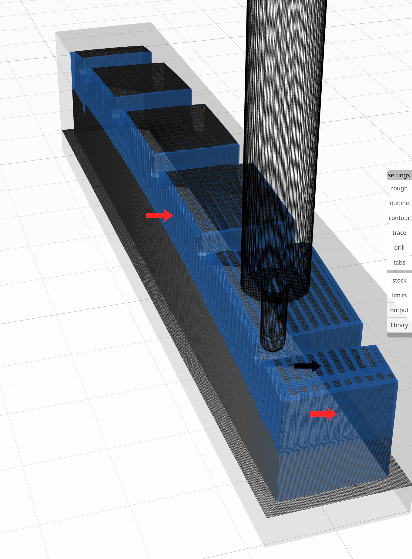
The other issue is the cuts into the side of the part, as seen with the red arrows. Are those the same bug? If so then nothing more to be done then leave it on the todo list.
I think the cuts into the sides are a tolerance setting issue. try reducing that value on smaller parts. I’m fairly sure the wide blue strips vs top and other side of the part are the rendering offset issue.
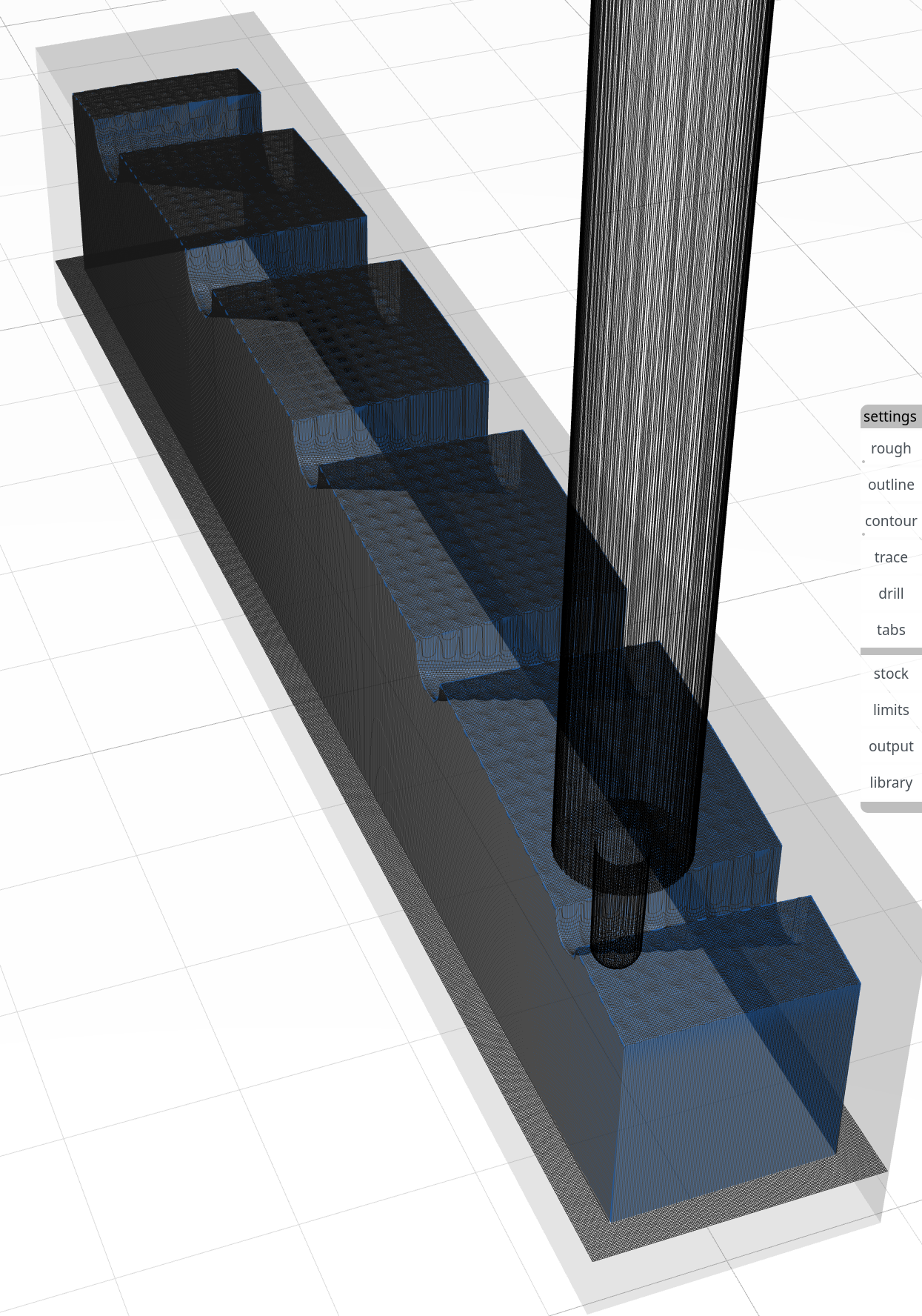
There are virtually no “solid blue” areas (i.e.: too much material taken off) and cuts in the side of the part are entirely gone.
So my only question now is whether there is some guidance on how to select the right tolerance value. For example: “should be less than 10% of the tool diameter”. If something like that can be added to the tool tip, even if it is just a rough guideline, it might help others from having issues like this.
Thanks again for the great work (and support!) on Kiri:Moto!
It’s really an issue of memory for computation. the finer the mesh (tolerance) the more memory (and cpu) squared is required. I think it might make sense to allow a setting of zero “0” which will automatically compute a tolerance based on the new animation mesh setting. that would give both a simple control (pulldown in preferences) and an “expert” override.
Sure, that sounds perfect. Always good when the tool makes smart choices for the user, and then allow the user to override.
I did notice that after I significantly reduced the tolerance it took substantially longer to slice – like a few minutes. However, all things considered, the slicing is still a small part of the total time to generate a part so I personally am OK with a precise part vs. a quick part.