Oh ok I see.
I’ll be using a Duet 2 wifi clone in mine, never used reprap before but it doesn’t seem overly complicated😊
I’ve only had bad quality SKR boards so far, have had to repair the two I have atm.
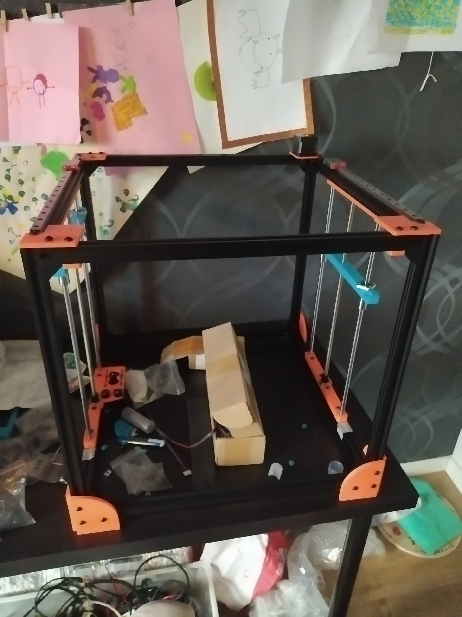
So, I’ve at last begun to build 
So far I’ve just gotten the frame up and some feet, but one thing I was wondering. Is there an easy way to get the frame square or is it just grabbing my square and start measuring every angle?
Perhaps I have been exceedingly lucky with the extrusion I’ve sourced, but I’ve never had issues with frames not being square after bolting it together with the angle pieces. That’s not to save I’ve been careless in assembly. But it’s been pretty clear when I did not put a corner together cleanly or accurately. And also easy to remedy with a loosen, push, tighten.
I checked the extrusions for faults and bad cuts and found none. Still find it tricky to get it completely square, I don’t know if there’s to much play in the angle pieces or maybe I’m just over doing it.
I’ve gotten it kinda square now anyway, and I’m thinking I’ll continue to build it and see the test print results later to see if I need to correct the frame.
Still waiting for the linear bearings…everything else has showed up. It’s itching in my fingers
And I’m thinking about changing the psu mount, mostly because it’s gonna look very silvery when everything else is black and orange. Will print another cover to fit a larger fan anyhow.
Well it’s going forwards very slowly.
But now I’m kinda stuck with the bed mounting.
I have a Cr10 bed, more or less, so I don’t have any extra space for the mounts outside of the build surface. The screws are not very long and quite far from the edges. I was thinking I could have mounted the bed with the screws going through the aluminium bed holder profiles, but the screws are too short… And I still can’t print longer than 240-ish mm.
So right now I’m thinking of mounting the bed without the possibility of manual leveling(to begin with).
if you get 1/2" square tube or even wood, you can get long enough M3 screws to go straight through the tube and held in place with a nut on the other side. I’ve done this with other builds in the past. Works well and material is cheap / easy to come by.
Yeah, the problem was, at first, that 1/2 inch (12,5mmish) is hard to find in Europe so I had to go with 15mm. And while it might be possible, it’s super tight pushing them through the aluminium profiles.
I’m toying with the idea of placing 2 more profiles(or something) across from one profile too the other and line up the new ones with the screws on the build plate. Or maybe modify the Z bars so that I can move the 2 aluminium profiles closer together, because right now the screws line up with the inner edge of the profiles.
Thanks for the tips btw!
This might be a stupid question.
How important is it that the idlers in the front(top) exactly line up with the idlers on the X axis(Y plane)?
Because my rails have are a bit different from yours, the idlers on the x axis would end up 8mm further in towards the center on each side. Otherwise I will have to try and drill them or remake the front (and back?) idler/motor mounts.
I’m still using the 400mm rails, but have redesigned the x axis mounts a bit. Not all mounting holes are shown here but I think you get the gist.
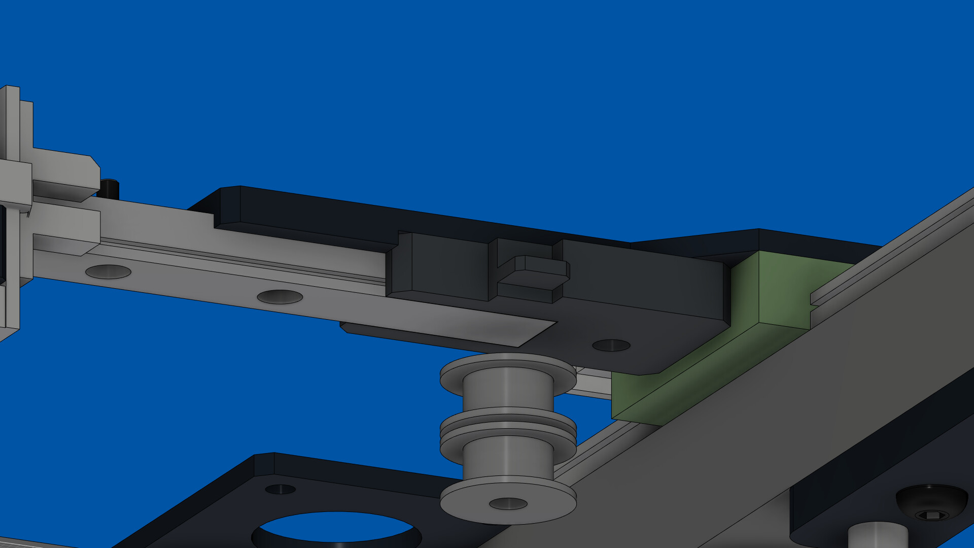
hard to tell from the pic, but the belts may end up running on themselves in some setups
Yeah, I’m hoping I solved it by moving both front idler mount and x-axis mount inward 8mm. So everything stays square.
Now I just need to figure out how to drill the hole in the rail from 3 to 5mm so that the idlers can be mounted.
brave or crazy. never considered doing that
1 Like
Drilling did not work, don’t have drill bits hard enough. Ended up slowly filing with small rotary diamond file and that worked a treat
I’ve been looking through the pics you uploaded above but I cannot seem to figure out how you mounted the X-axis idlers. Is there a spacer above the idlers? A small shim or something in between them?
Thanks!
I put a thin washer between the idlers, but nothing above in most builds.
1 Like
I have no prior experience off corexy and I have been reading up on the theory.
I was wondering if you have been working on some other kind of belt holder for the hotend assembly? Or do you think that the solution you have now is the best one?
I’ve read about the preferred tension and the hertz it produces. Any other suggestions for tensioning the belts?
Are you looking for a solution that provides greater tension? Or a more refined approach?
I don’t know really 
Right now I’ve just placed the belts in place but I’m a bit unsure of how to get the level of tension needed, by just pulling and trying to get the strap/strip to hold.
If there is some kind of belt anchor that is easier to handle and tension.
But maybe I’m over thinking things.
I’ve never had a problem achieving proper tensioning. Maybe it’s technique. I use zip-ties to hold the belt with teeth facing teeth. Two zip ties are required to maintain tension without slipping.
1 Like
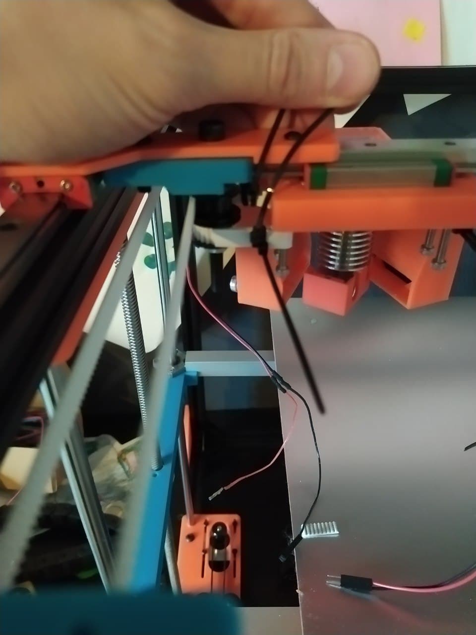
Thanks for your patience Stewart!
I’m currently looking at the endstops among other things. And it feels like the range of the hotend assembly is limited by the zip ties on the belts. I realize I haven’t cut the zip ties down to size yet, but even so it feels like the hotend won’t be able to reach the entire bed (missing maybe 20mm on the outisde of the bed). Have you had any issues with this? I cannot really push the zip ties further in either.
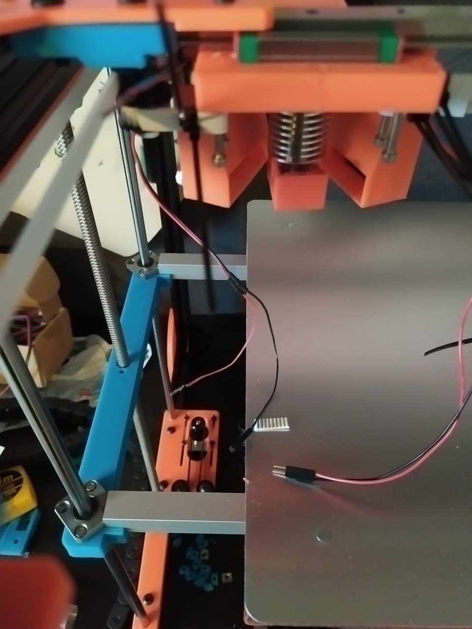
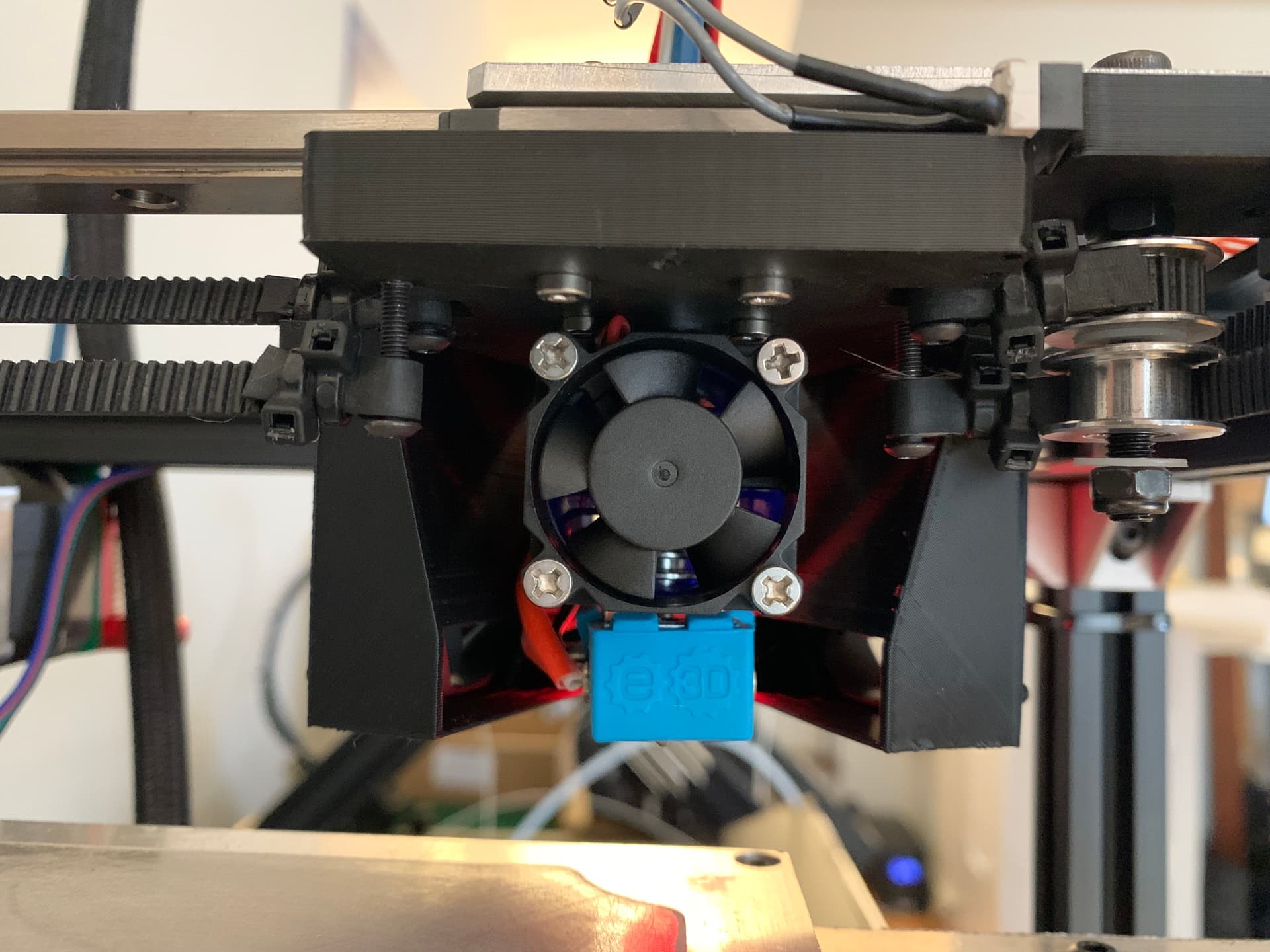
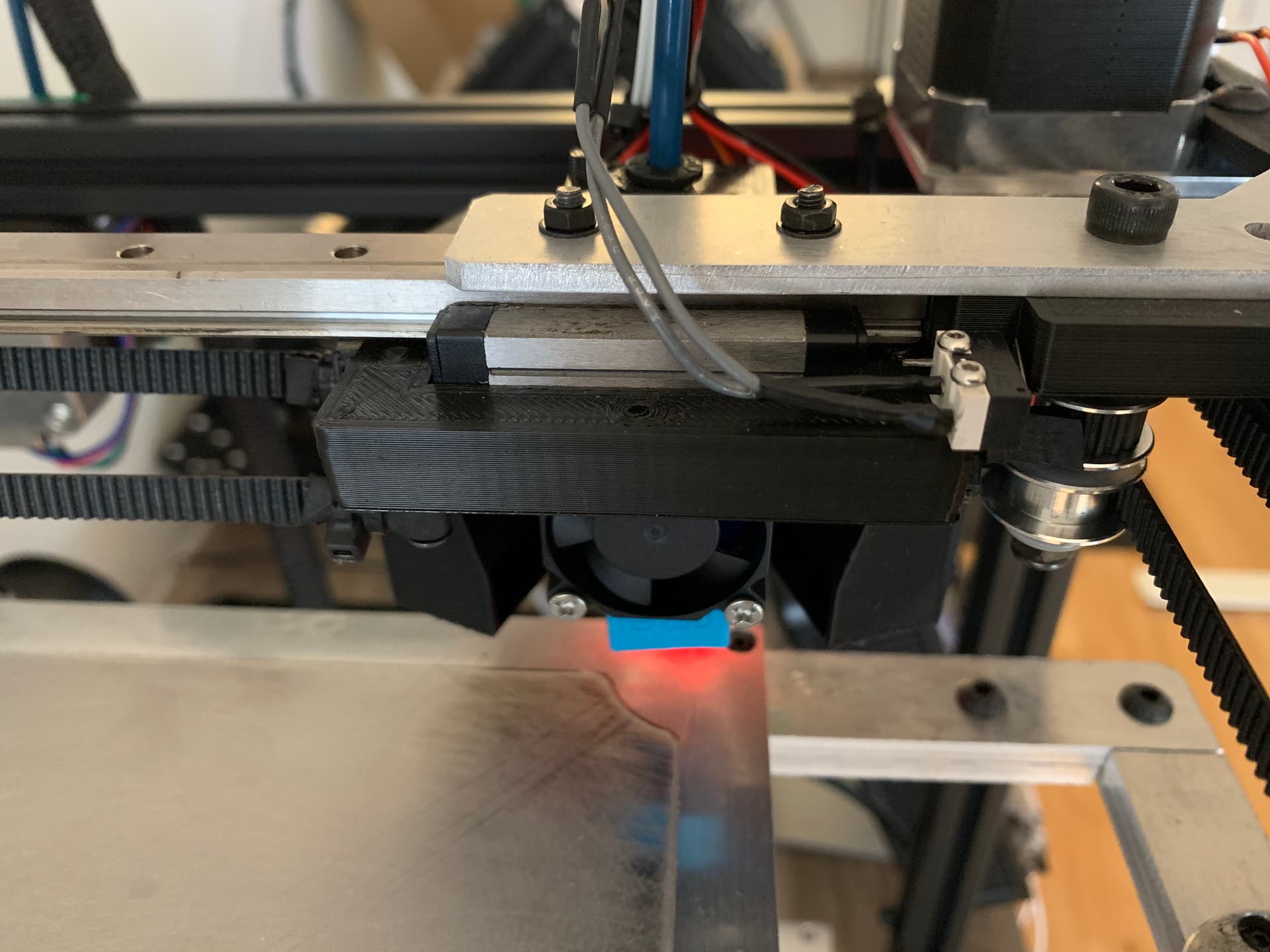
Is this the head setup you’re using? My heated bed is 330 x 330 and the magnetic removable surface is 300 x 300. You can see the nozzle lines up with the corner of the build plate just before the zip ties contact the idler.
Yeah yours look very nice.
Yup that’s the head Im using.
Forgot to add that my bed (and entire platform) is 310x310mm.
Maybe I need to cut them even shorter. I’ve also used to long screws apparently. Mustve missed that.
Thanks!
Edit: Your base for the hotend assembly on your last pics, is that the same on as on the 2.5 beta? It looks a bit different, but it might be the angle or camera playing tricks. And the screws are m3?
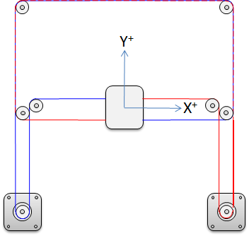
Because the belts are oriented like this right, except stacked on X-axis?
Edit2: Oh crap, now I know what the problem is. Dunno why I didn’t realize directly. Since I went with 400mm rails instead of 350mm. I had to move the X-axis idler pullies inward about 8 mm…
I’m sorry to have taken up your time!