Hey,
so I’m in the starting phase of my build and parts are still coming.
But I thinking about some things.
Edit: strike that about mirrored hotend assembly, my brain is a bit mushy.
Also, have anyone remixed any other fan shrouds/direct drive assemblies?
Since I’ve only got a modified Ender 3v2 at home, I cannot print the parts for the cover for the electronics (and I can’t afford laser cut parts atm). I was thinking I might split the parts and then glue(?) them together or has anyone solved it a different way? I don’t want everything just hanging on the outside.
I was having some other thoughts but I’ve forgotten…I will append when I remember
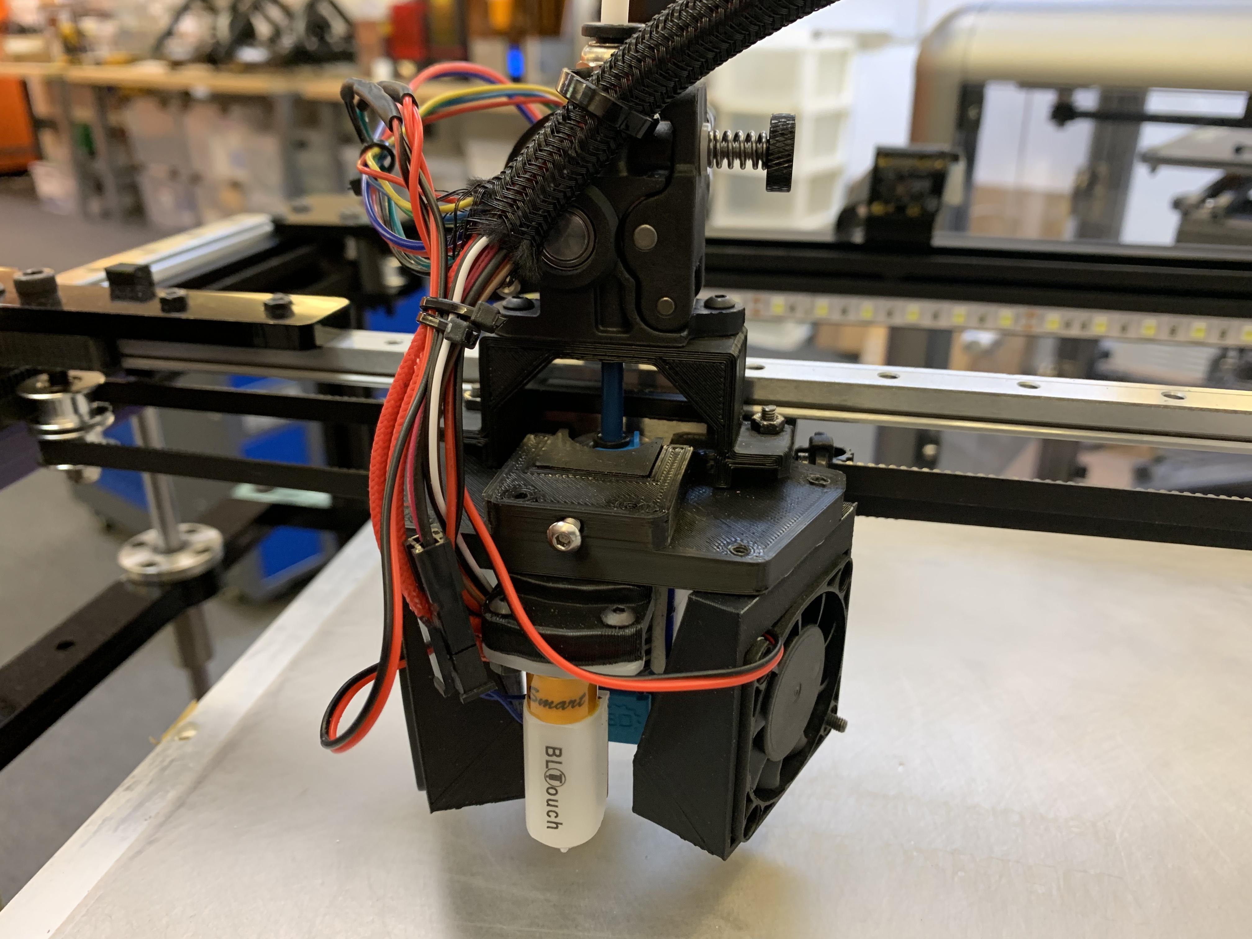
I made another direct drive configuration for the Orbiter extruder, but it requires changing to the GridBot 2.5 rail layout. I found that the BMG knock-offs were unreliable with dimensions so each one required updating the model
It’s a design I’ve been experimenting with over the last 18 months, but haven’t gotten it to the level of finish / detail of 2.0 – and so I have not made a public release.
Sure. Let me find the most recent CAD model and see if I can make it or a version of it public. While I really like the compactness and aesthetic of the 2.0 design, I opted for a simpler-to-make and possibly more rigid resign in 2.5
Whenever you have time and feel like it😊
Thank you so much.
Edit:
Should have read the other threads more closely. I found the 2.5 you shared in another thread, looks great! I’m now thinking I might opt for some kind of hybrid 2.0/2.5. Since I’m printing everything I’m a bit concerned that the bed supports in 2.5 would be stable enough(?)
But the optical sensor placement is beautiful, and I really like the smaller hot end assembly with the 5015 fan
Edit:
I’m trying to get the hot end “head” plate to work with direct drive, it’s a bit tricky and how ever I rotate the BMG+stepper they get quite un-balanced. Have you thought about direct drive on the 2.5?
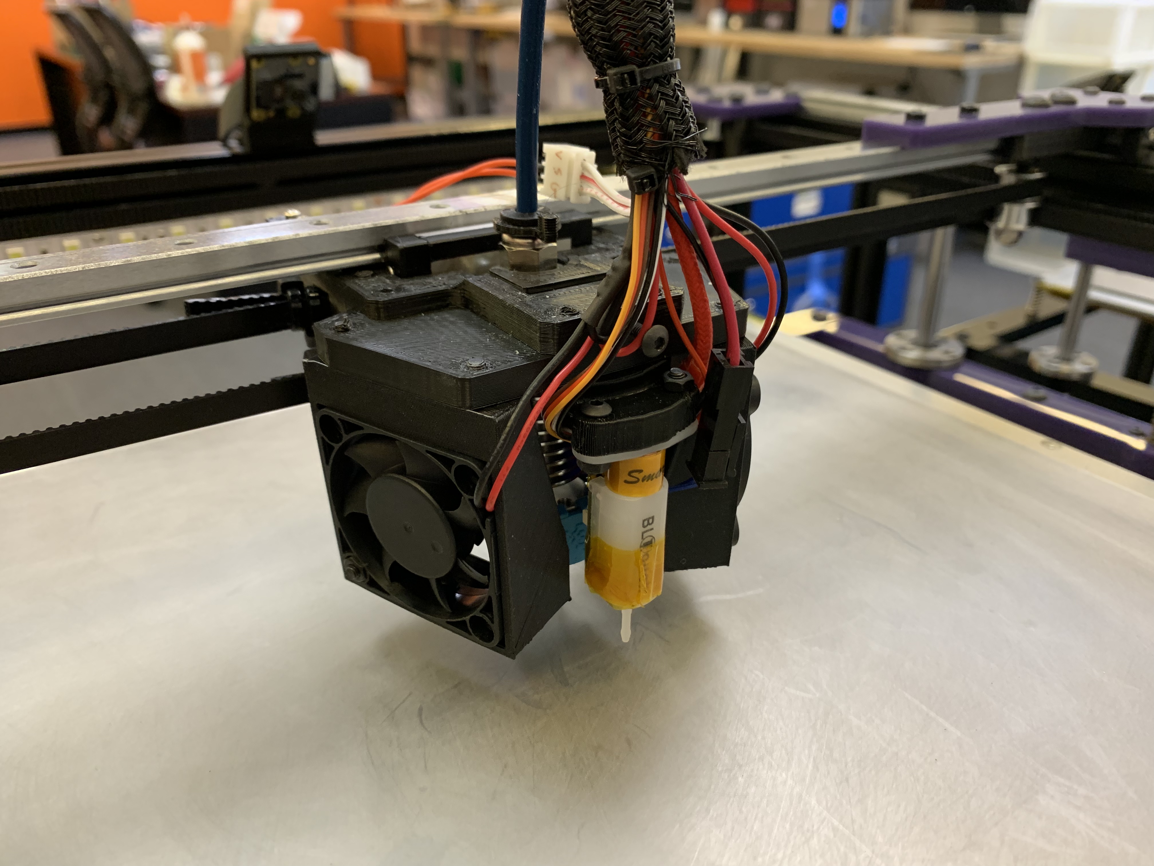
yes, the 2.5 model I hope to release later this week has a trivial adapter for the Orbiter extruder. I have both configurations working on my printers. will share pics.
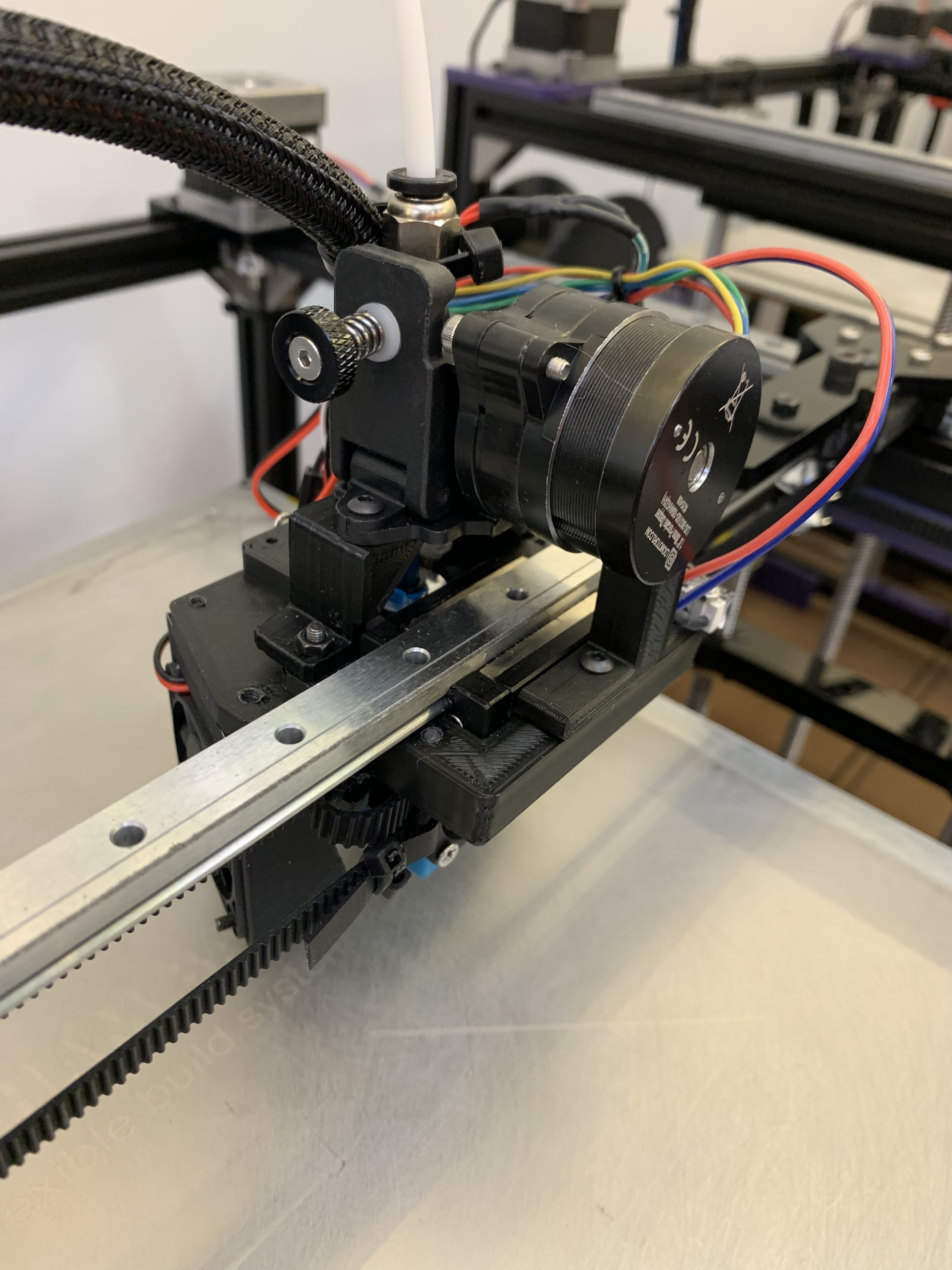
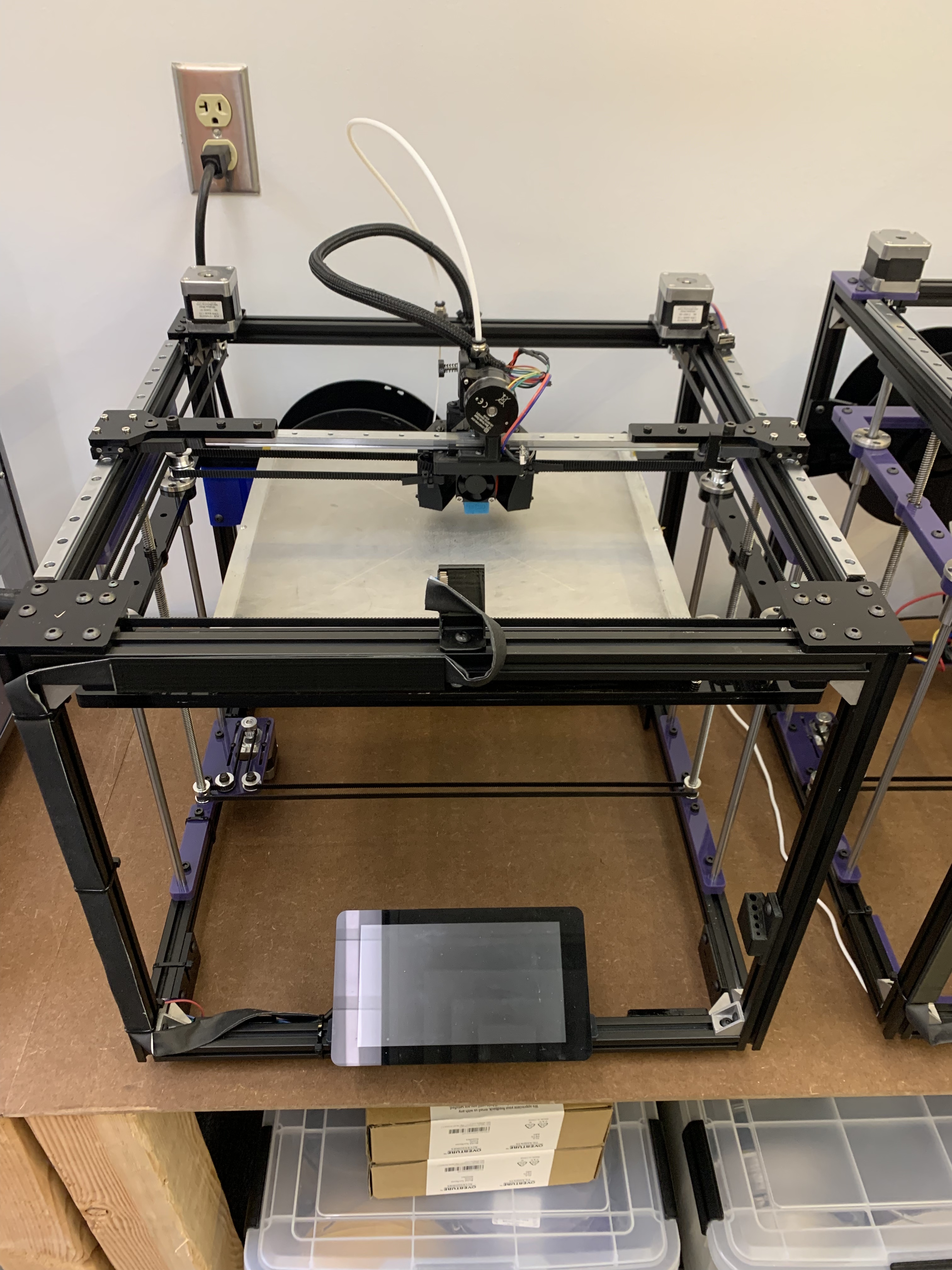
Here is a snapshot of the work in progress. I won’t be able to add pics for a couple of days. Major changes:
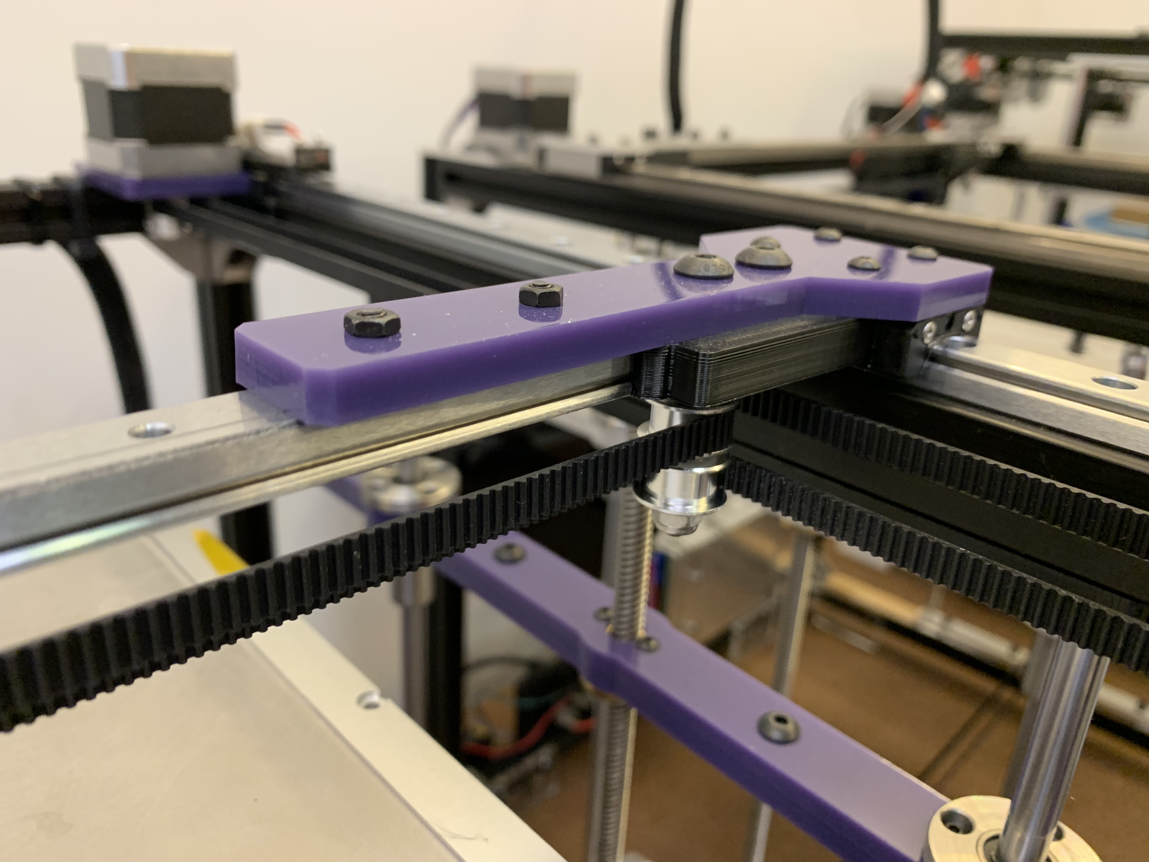
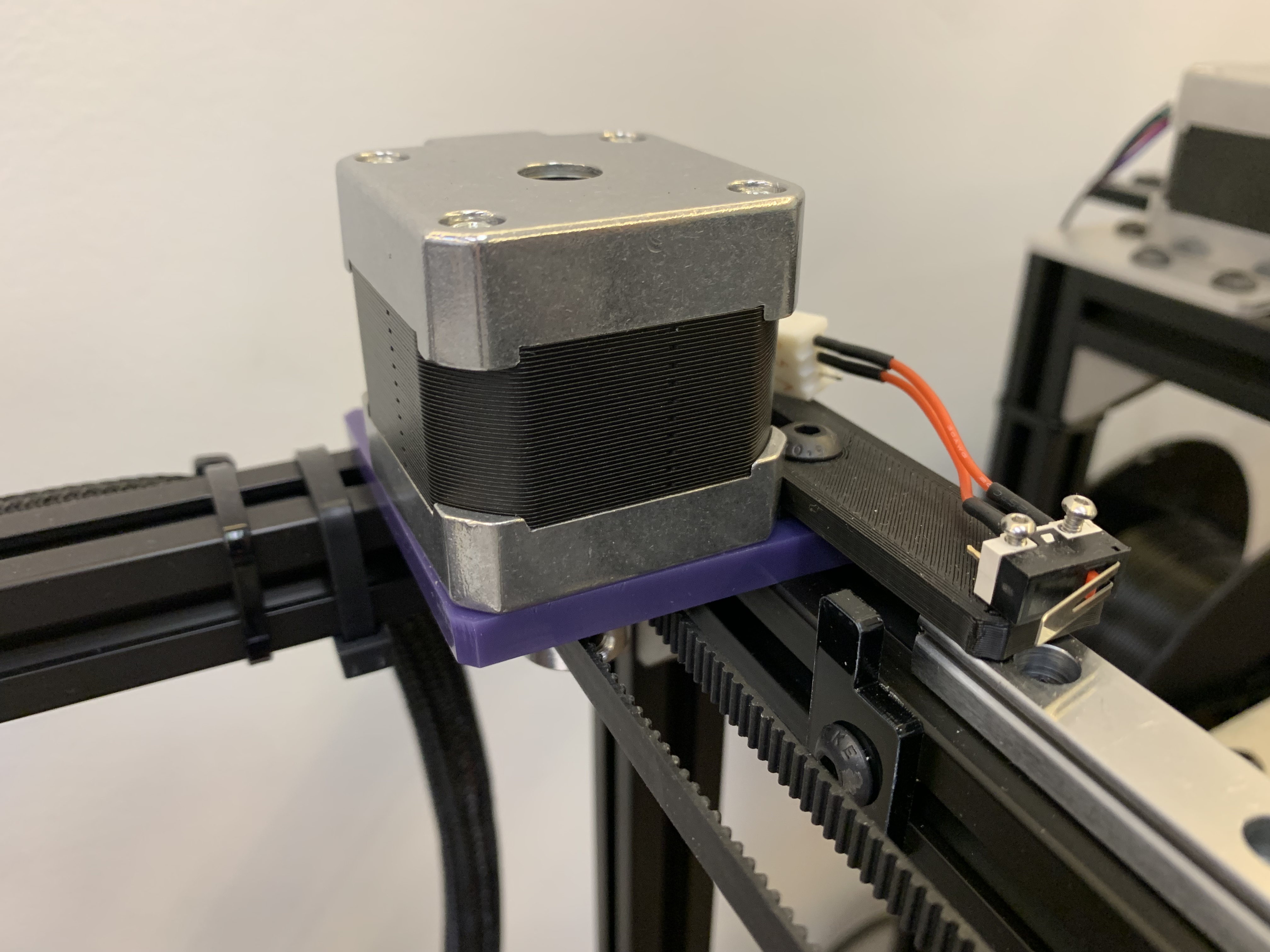
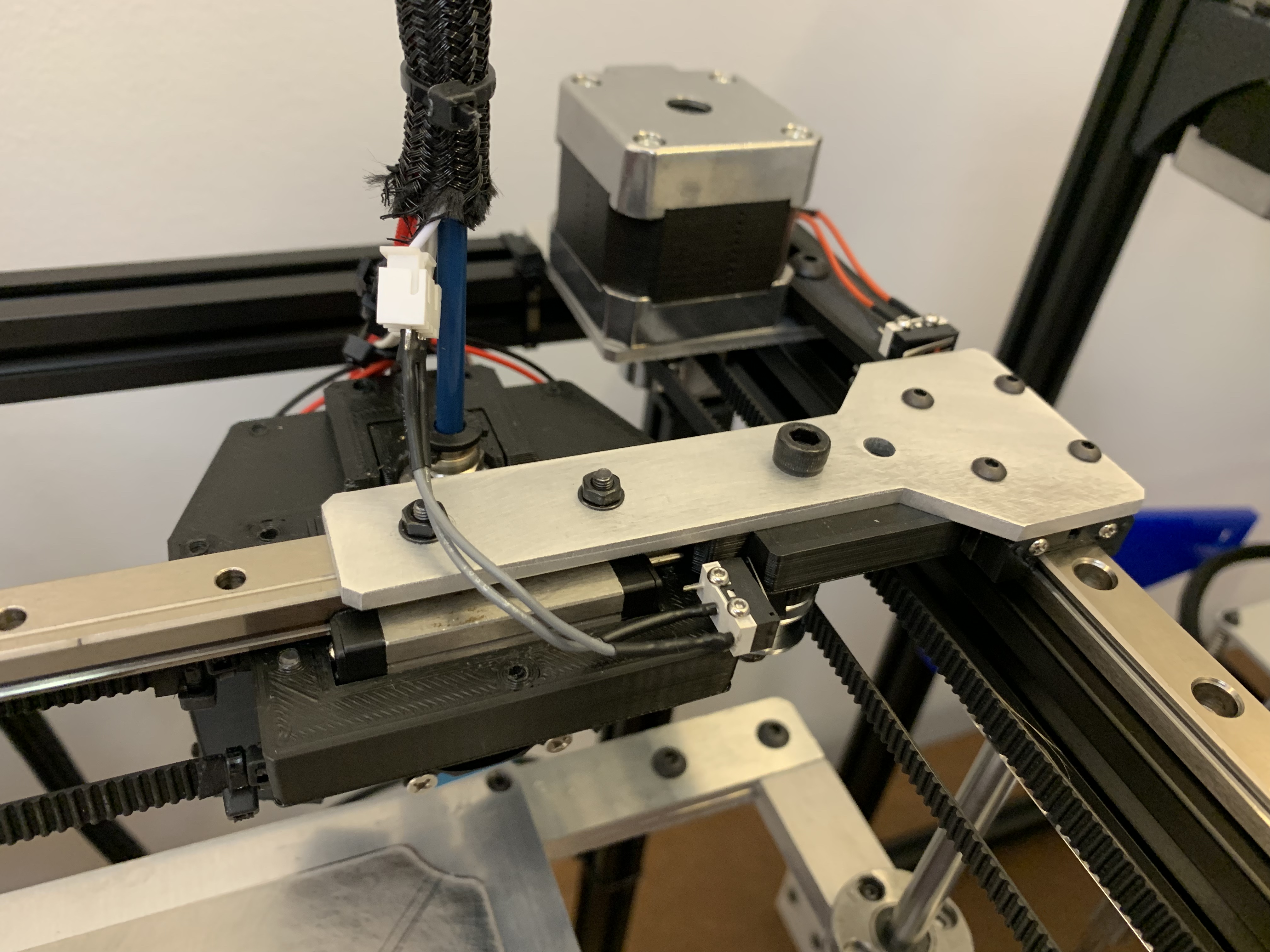
rails on top for better rigidity, simpler brackets
motors on top for the same reason
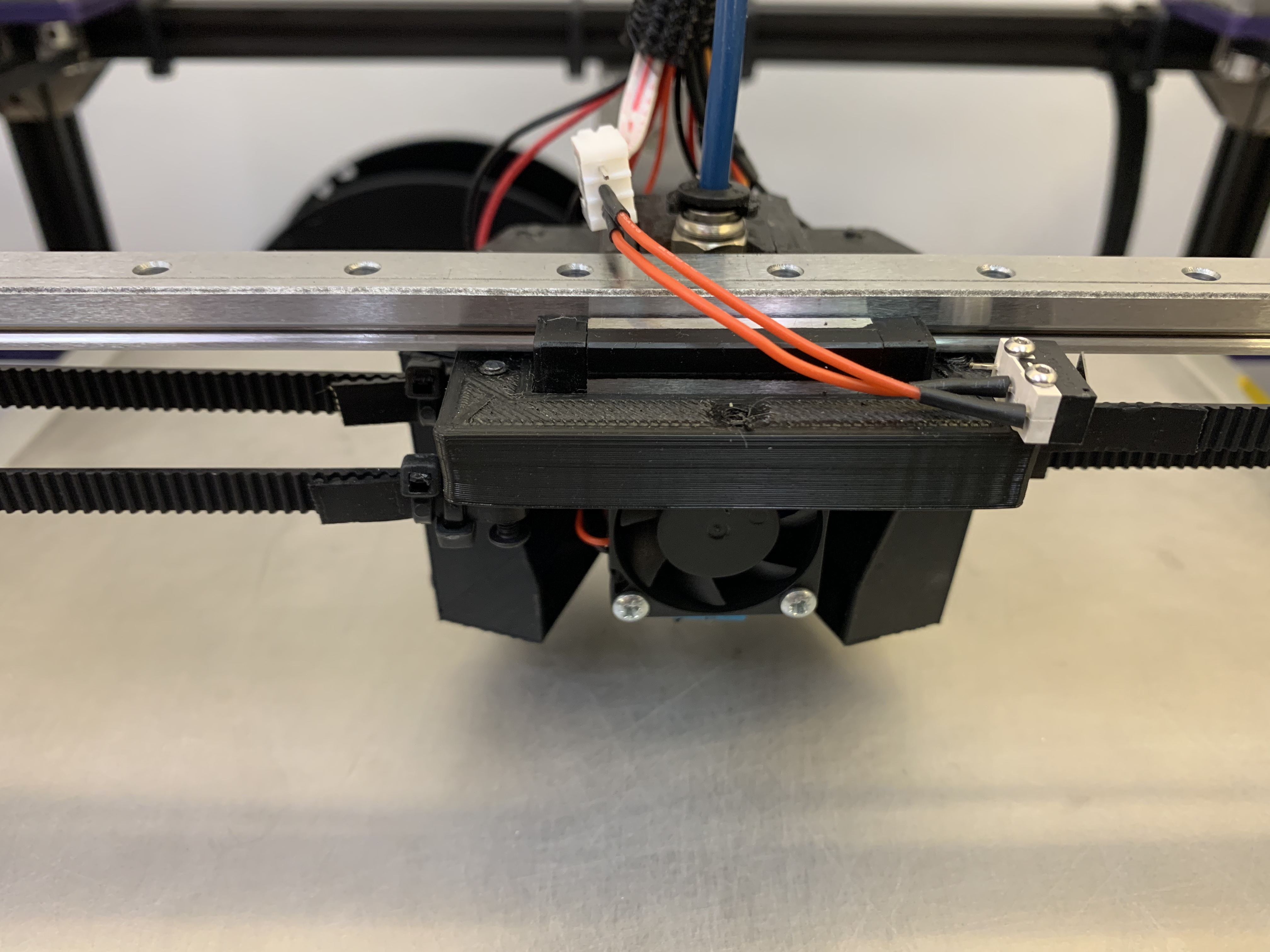
more cooling power with twin 40mm fans
switchable between bowden and direct with one simple bracket
X and Y endstops are now miniature mechanical instead of optical
Not pictured in the bed layout are the springs on the posts, nuts on top. Some explanation is needed for options around X rail brackets and the head. There are several ways to produce these parts.
Since I would be printing the z cross bars, I’m still unsure they would have enough stability. Might go with L-shaped bars in that case, or just use aluminum tubing like on 2.0.
And while the orbiter seems like a brilliant piece of kit, I can’t really spend more money atm I might try a Superfly (https://www.thingiverse.com/thing:4841682)
Do you feel like that cooling solution with 40mm fans(1 or 2) work well? I’m just curious because it looks a bit like the hot end heating block would get quite a lot of air blowing from them.
The X bar looks very neat like that, very nice.
I’m guessing you’re going to add some kind of belt fasteners, or will the belt go around the screws on the X axis?
Thanks again! Beautiful work!
Edit: and some kind of spacers on the front pulleys, or is that not needed? So that they won’t chafe against each other.
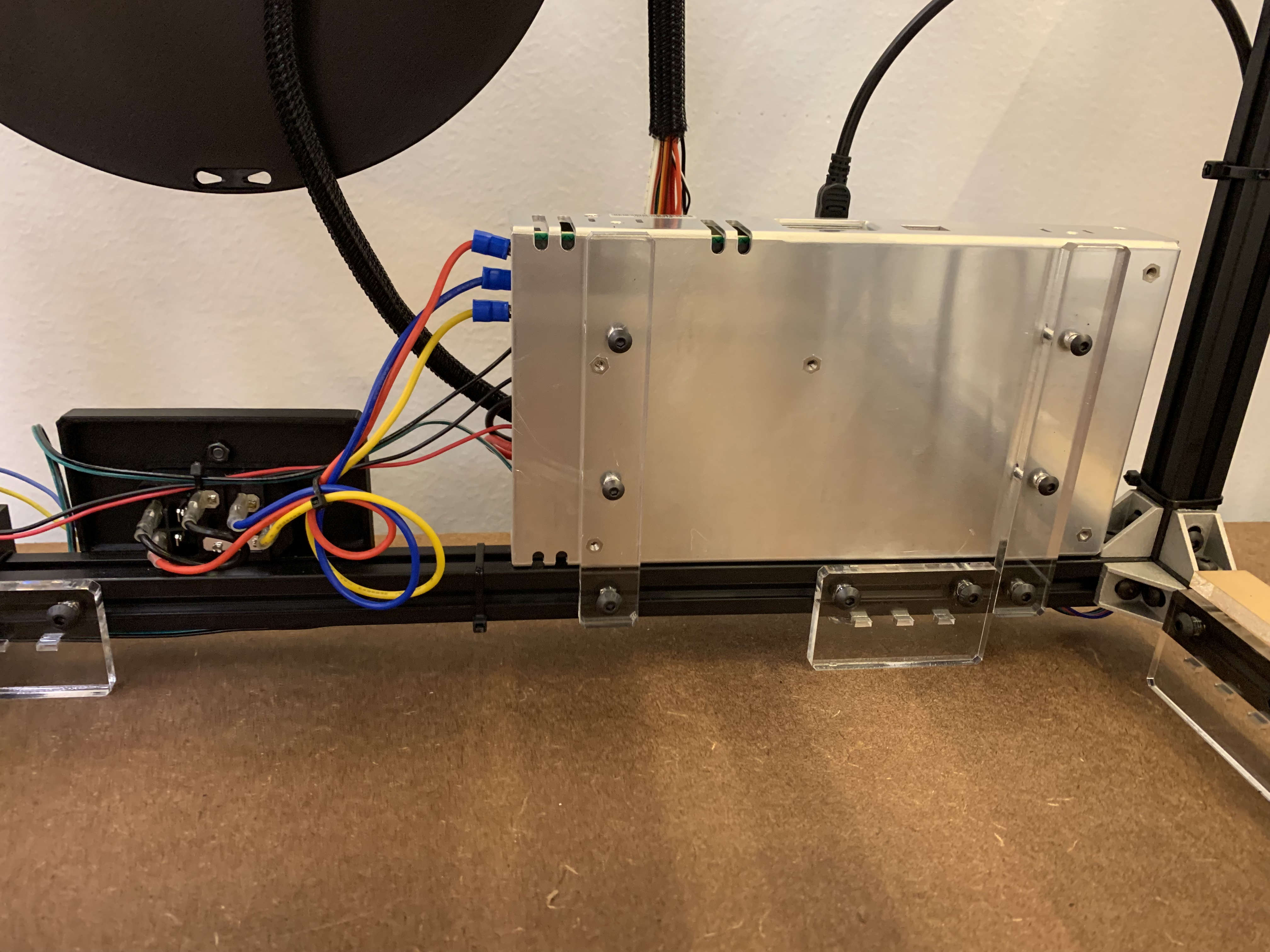
Edit 2: I’m finding new things ! The power supply mounting looks like it can become quite cool. Also, great idea with light bar.
Edit 3: Sorry I have too much time on my hands. I’ve been thinking about the linear guide orientation on the X axis, why upside down? The change on the Y axis I can understand. Wouldn’t having it upside down put more strain on the block (or maybe they work better that way, I don’t have any experience with linear guides)?
the cooling situation is much improved. the ducting forces air down toward the nozzle/part/bed, so it does not cause heating issues in the hot end. and it’s required for high speed printing. you can always throttle it if it’s too much for your print.
I’ll send pix when I’m back in the lab in 2 days. I did put spacers between the pulleys.
Mounting the rail upside-down makes the connection more direct and solid. It does not affect the function of the rail.
Yeah, it’s just because a 5015 radial fan seems to be the go to part cooling fan (I’m using that on my Ender). I was just curious since I haven’t seen that fan shroud before.
Thanks for the rail explanation
The radial fan might be more compact depending on design, but requires more complex ducting to get full part cooling coverage. And the total amount of airflow is lower in that setup. So it’s ok for modest/slow printing, but not great for fast (100mm/s+) or hot.
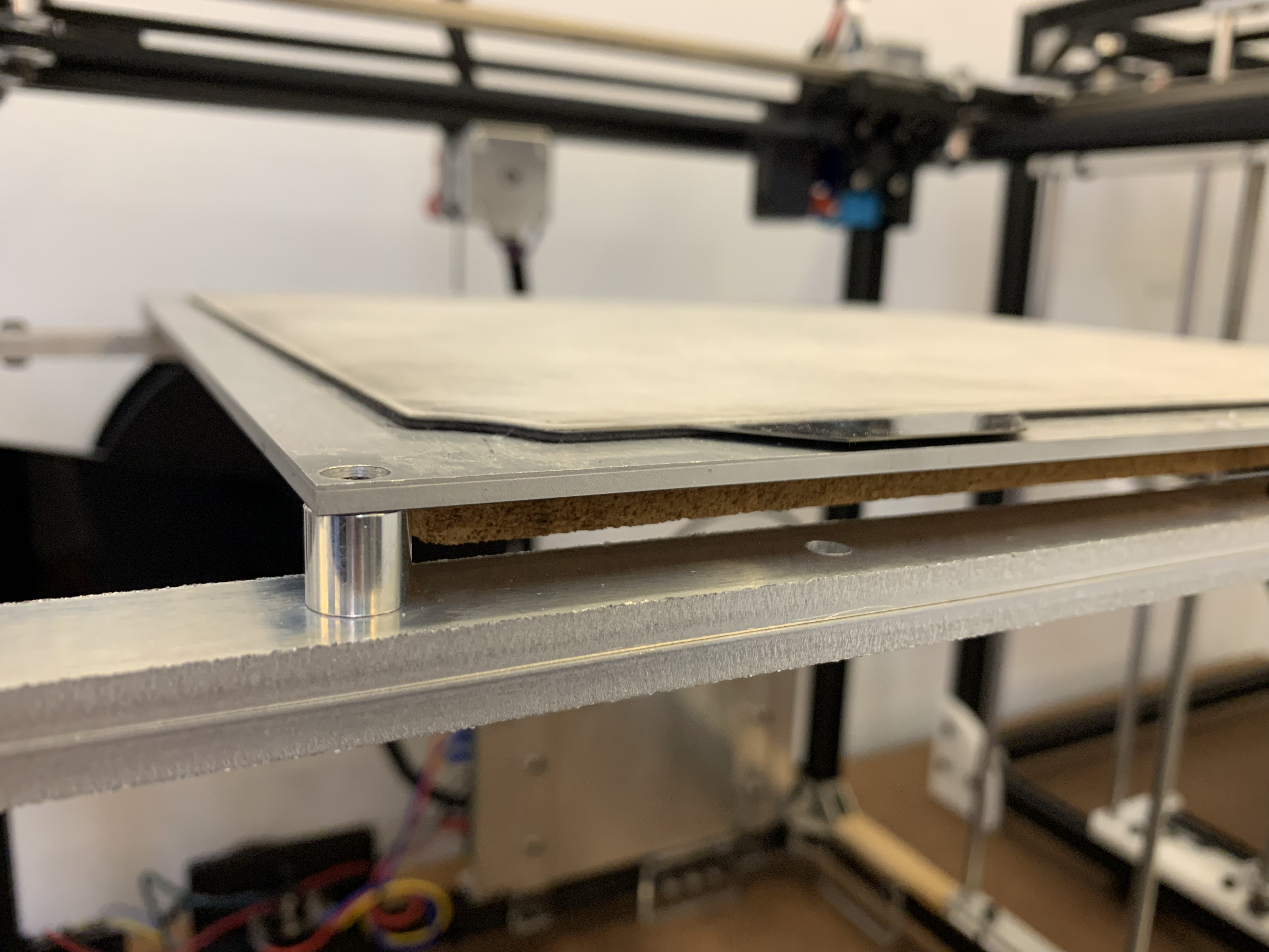
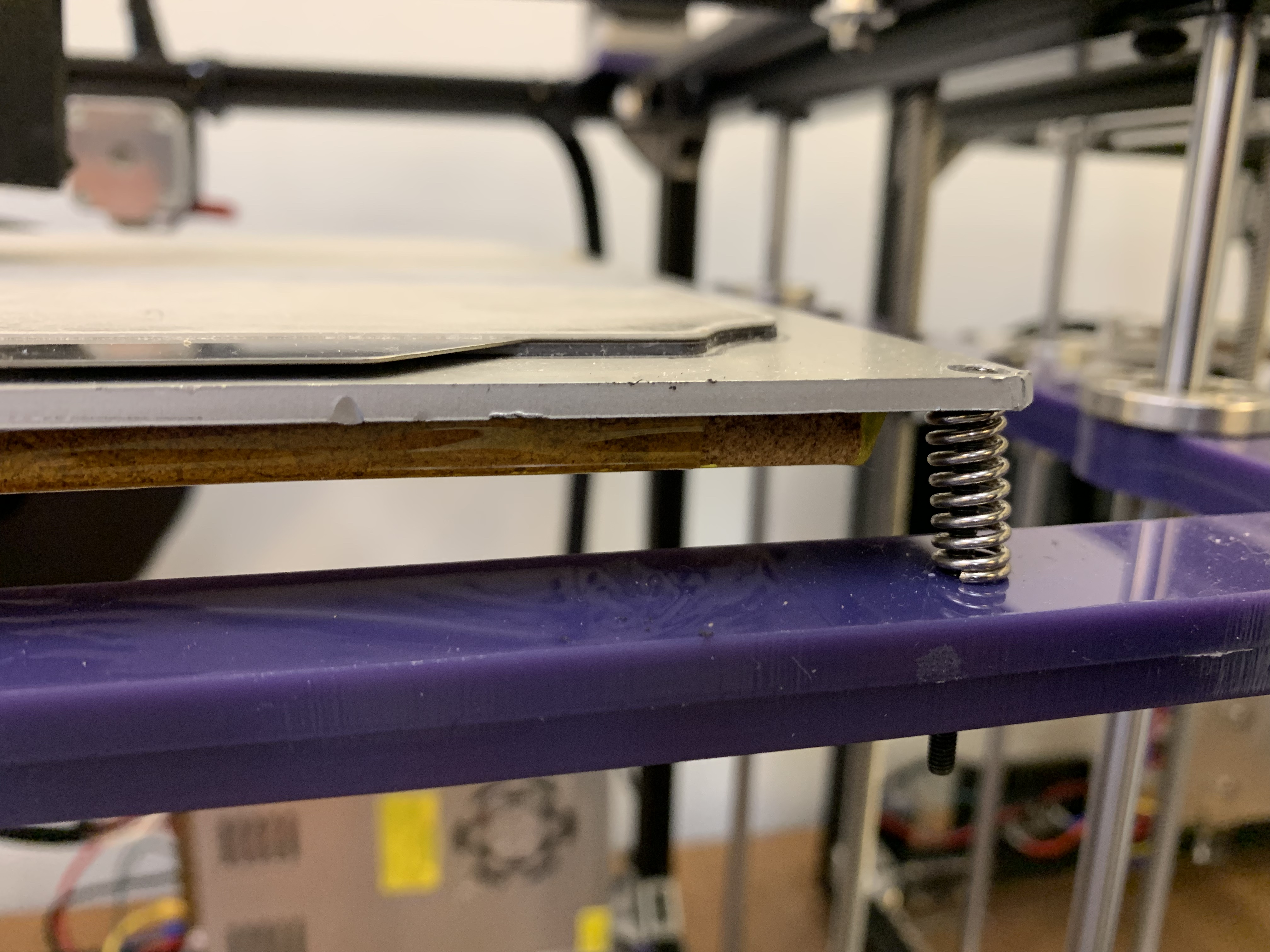
I´m trying to figure out how to mount my bed, since the screws are mounted directly on the aluminum bed. I’m also unable to print longer pieces than around 230mm.
The aluminum tubes I found was 15x15mm (could not find 1/2 inch).
So this is what I’ve done so far, not that I’m sure this will work. I’m thinking I would have silicone or regular bed springs between the bed and aluminum tube. I’ve also made the “Z middle” parts 1mm longer on each side to account for wider tubes. Will probably need to add some small shims between leveling knob and tube.
Of course I’m not expecting anyone to solve this for me, I’m just wondering if this would be an acceptable solution?
Edit: just realized that the leveling knob is upside down…Sorry about that.
Edit 2:
Or just keep it like yours more or less. Might go with all 4 corner though and I’ll probably need longer leveling screws.
I bunch of pics of 3 different GridBot 2.5 betas. Shows bowden, direct, endstop, bed mount types (and shortcuts), psu mount, etc. All what I would consider prototypes and tests of different ideas.
Thanks so much for all the pictures! Very inspirational.
What made you switch from optical to mechanical endstops? Except that it’s easier and smaller I guess
Also saw that you’ve gone from 400mm linear rails to 350mm. Made it a bit tricky for me since I’ve already ordered 400mm.
a couple of reasons for the use of mechanical endstops. yes, they’re smaller. but primarily, it removes the need to place and calibrate a trigger. also, it’s simpler to wire. given global supply shortages and products being discontinued, I was not able to get the same SKR boards as before. I went with the E3 turbo and it is not easy to fit optical endstops with that.
I did not need more than 350mm of travel in X or Y, so moving to a smaller rail opened up some configuration options.


 I might try a Superfly (
 ! The power supply mounting looks like it can become quite cool. Also, great idea with light bar.