Nesting
KM is really great for nesting as it can almost automatically generate the NC code for a large set of items (aka widgets). This is a huge benefit in most cases, especially when some items of the nesting have later changes to incorporate. KM already outperforms a lot of (even commercial) tools out there in speeding up this process!
However, some (maybe) minor features could make it even more powerful here.
I want to share my findings about nesting and post some code that helps me with this task.
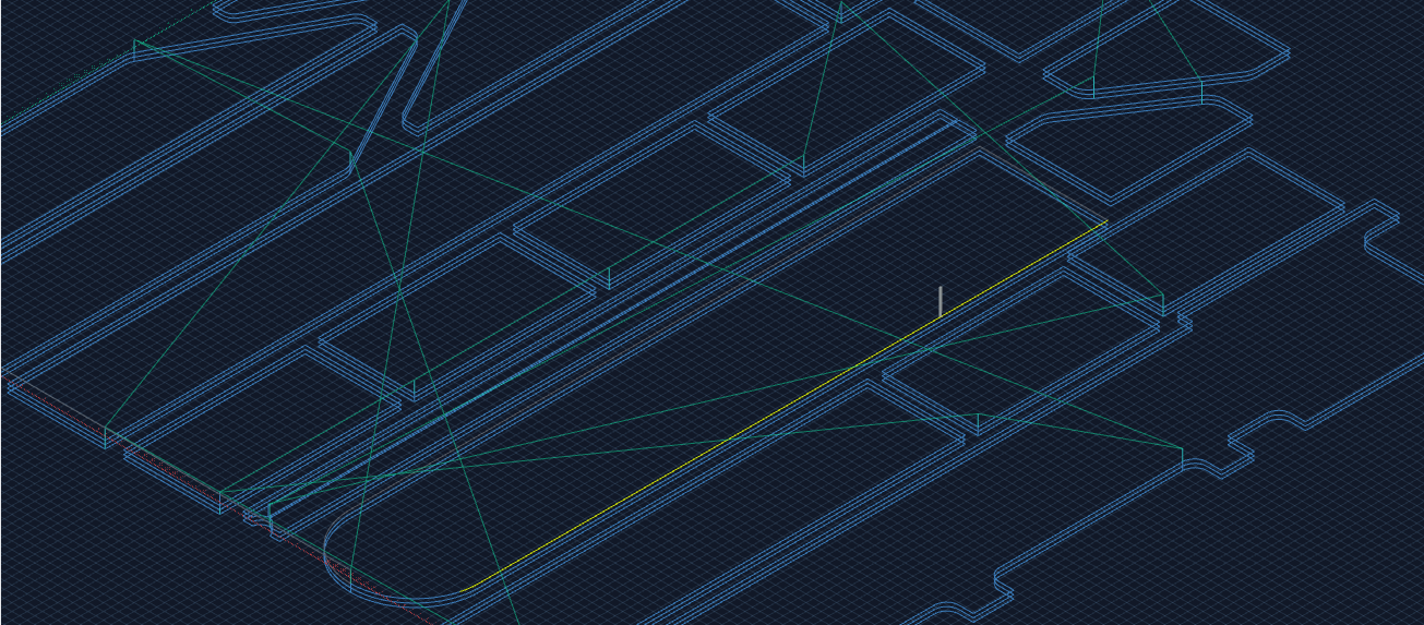
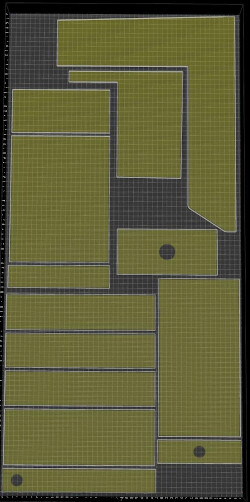
Preparation: I set the machine workspace to the size of the “sheet” of wood (stock material) to fit the items inside the right boundaries and do the Nesting - which still can be quite challenging sometimes.
Here is a rather simple exmple:
- Alignment
When you put lots of parts into one “sheet” of wood (furniture front parts for example) you want to align the parts, so the texture is continuing properly from one item (e.g. a drawer front) to the next. This does the trick:
kiri.centerWithFirst = function() {

	const aMeshes = api.selection.meshes();
	if(aMeshes.length < 2) { return false; }

	//get x of first:
	const x = aMeshes[0].widget.track.pos.x;

	//align all others to x of first:
	for(var i = 1; i < aMeshes.length; i++) {
		aMeshes[i].widget.track.pos.x = x
	}
}

kiri.centerOnX = function(x) {
	const aMeshes = api.selection.meshes();
	for(var i = 0; i < aMeshes.length; i++) {
		aMeshes[i].widget.track.pos.x = x
	}
}

//To do: did not yet figure out how to trigger a refresh of the space from external code
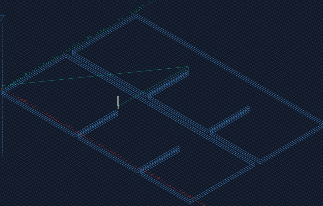
- Distance
You also want to have the items placed with equal distance (either in x or y). The distance can either be as low as the tool diamater but most likely you want some material left between items. This material will hold the item during the last few centimeters of path at the end before the part breaks loose. Tags are possible but can be nightmare with laminated material (Risk to ruin the laminate at the bottom) (relates to “Order of items” below)
//requires to select the item with minimum y position first. To be improved...
kiri.equalYDistance = function(dy) {

	const aMeshes = api.selection.meshes();
	if(aMeshes.length < 2) { return false; }

	//get x of first:
	var y = aMeshes[0].widget.track.pos.y;

	for(var i = 1; i < aMeshes.length; i++) {
		y = y + (aMeshes[i - 1].widget.track.box.h / 2) + dy +  (aMeshes[i].widget.track.box.h / 2);
		aMeshes[i].widget.track.pos.y = y;
	}
}

//To do: did not yet figure out how to trigger a refresh of the space from external code
- Order of execution
3.a. Tools
Usually you have a large diameter tool (lets say 8mm) for the outline and some pockets, and 4mm for details and holes. To prevent lots of tool changes it is helpful to have GCode output sorted by Operation (aka Tool) first and then by item!
3.b. Items
It is also important to specify the order of items in execution. The aspect about Distance mentioned above gets less important when you can define the order in which items get cut. This way you can ensure that there will be enough stiff material around to keep it in place until the last second of outline cut.
What would be the best approach for implementing this? It is easy to select items/widgets in the desired order. Is there an array to sort somewhere? Or is the better approach to remove the widthet an readd them?
3.c. Inside first
As discussed in How to clear large holes. Helical vs Trace, this feature is already present. I vote for enabling it by default: I cannot see a benefit for cutting any outline before the pockets as the item is already loose after the outline cut. At least this is true for nesting.
3.4 Outline startpoint at minX/minY going clockwise
Here is another issue about the outline: When a part is very close (less than tool diameter) to the edge of the stock material, it is important to ensure that this side is not last one in the outline cut. If it is, the part will break loose right before and will fail. Having the option to force outline to start at minX and minY would do the trick. Ok, this might come with some extra cost of travelling time but makes lots of tags obsolete!
Even more: Forcing the start point to minX/minY together with specifying the order of items would allow a minimum Distance (see above) of tool diameter between items without the need of tags (depending on material of course). Would be too good to be true… ![]()
- Autoselect bottom edge of pockets/holes for trace operation
As KM can already highlight all edges and make them clickable, it would save a huge amount of time to automatically selecting all inside (pocket) bottom edges for a trace operation. Especially since adding/replacing an item resets all selections made before. Imagine you have 100 little holes of 4.7mm that you cannot drill but trace and then you figure out that you have to change another item within the nesting. You will start at zero and again selecting all 100 bottom edges over and over again!
Sophisticated feature: It would be helpful to somehow ensure that traces of larger holes get not picked up by more than one trace operation (the ones with smaller tool diamater). Assuming that we have a 4mm and 8mm trace operation, autoselecting the 8mm traces first could exclude them from getting picked up by a 4mm trace. But this could be a tricky one…
- Fixed origin
Maybe this is possible but I could not figure it out yet: The work area adjusts automatically to the minimal area (min box that fits around all parts). If I delete an item that defines either minX or minY (leftmost, bottommost), the box will resize and the origin will move. A workaround for this is not to delete items but do disable them. But this is not always reasonable. However, I think being able to setting the origin fixed to the minimum of the machine workspace (bottom left corner of entire workspace area) could be valuable.