I really like the simplicity of this and wanted to ask if a new machine would be possible? Shaper Origin is a handheld cnc mill that works with svg’s only so what would be needed is a hybrid of the CNC mode i.e setting z0 at the top surface and then features of the laser mode where it takes a 3D model and slices it into specified thicknesses. The output would need to retain the depth from z (Shaper has custom svg tags for this) and contain a custom anchor (Shaper has a red triangle for this) and a single stacked svg with those depth tags.
Again thanks, this is an awesome piece of kit here!
Hi,
The end result is a svg where each path or slice has a depth assigned to it. The laser comes very close to this when you check the Fixed box but the export contains nothing in either svg, dxf or gcode. Any of the other options like merged do create a usable svg but all the depths for each path is zero making it very difficult to do something like a topographical map. Unlike a laser where each slice would be cut individually and physically stacked and glued, I would like to start at the top of the model, mill the first depth, move outwards a little to the next slice, adjust my depth etc etc cutting each slice in place out of a single thicker chunk of wood.
can you provide a link to their custom SVG markup? it should be relatively easy to get this done in laser mode by properly annotating the Z layers then reversing them on output.
They don’t publish it and there is only four right now but their homegrown editor uses the following:
shaper:cutDepth=“0.75in”
The encoded depth to cut in either in or mm
shaper:cutType=“outside”
How to cut on the path with possible entries here are outside, inside, online , pocket and guide. Outside would be the default if you didn’t want to bother with this.
shaper:cutOffset=“0in”
How far the bit is offset from the cut line in in or mm. Online cutType will ignore this
this will require some experimentation. will it accept a 0 tool dia? will it accept measurements in MM instead of imperial IN? is the path expected to be imperial?
Hi,
Yes “in” or “mm” is how it accepts real world units
For the tool diameter it’s not exactly used at this point on import to the tool. Meaning it can be left out or you can future proof your end by including it. It will accept a 0 for the tool diameter no problem.
Polyline is also no problem and the tools seems to accept that just fine too.
I did misspeak earlier when I said the default cut type was outside when I should have said online. Having that shaper:cutType=“outside” tag in there would be very nice even if it wasn’t presented or used in the GUI.
The kerf will handle the tool radius offset. Given that is it OK to use cutType online? I was going to set the tool diameter to 0 then it doesn’t matter as long as it doesn’t crash their software.
Tool diameter shouldn’t crash anything as far as I know, it’s ok to be in the file but for right now the tool just ignores it. Maybe in the future they will utilize all their tags to the fullest.
The only ones that it does pay attention to on import are the shaper:cutDepth=“" and shaper:cutType=“outside” tags. The other two can be leftout for now or added and not used if you want.
I should add that this one is a little different from other cnc’s I know about in that it does it’s path processing on tool.
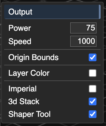
If you’re ready to help test this pre-production code, you can load it from https://dev.grid.space/kiri … this is going to load slowly since it’s not bundled for production. but you should see new laser options. You can try with and without imperial checked to see if “in” vs “mm” makes a difference.
Holy smokes! you are amazing for working this quickly!
So this doesn’t work on first go, it will not even display anything in a svg editor like Affinity Designer 2
As a new user I cannot attach files so here is a dropbox link
ImageToStl.com_CA-linear-dual-v2-p4.3.stl is the sample stl I am using
ImageToStl-Merged.svg is the standard run through as is which does load onto the machine
ImageToStl-Shaper Origin.svg is the result of testing the Shaper specific settings and does not load and gives an error
origin-export-1.svg is a svg exported directly from the Shaper software called Studio
Ok, reload and try again. It was missing the xmlns declaration and the path used an incorrect label. Is the red triangle origin necessary? And if so, do you have a recommendation for auto-placement?
You may need to hold down the shift key and click reload to clear the cache.
The red triangle is a custom anchor. When the svg is loaded to the tool it will use the ninety degree corner as the 0,0 of the svg. This allows for customizing placement beyond the standard nine anchors. If I were to recommend including it I would say in the grouped view where everything is all laid out and each path would have their own custom anchor in the exact same reference spot if that makes sense. Kind of like if you created a vertical triangular tube next to the design so each slice would also have a triangle slice in the same relative spot on the overall design.
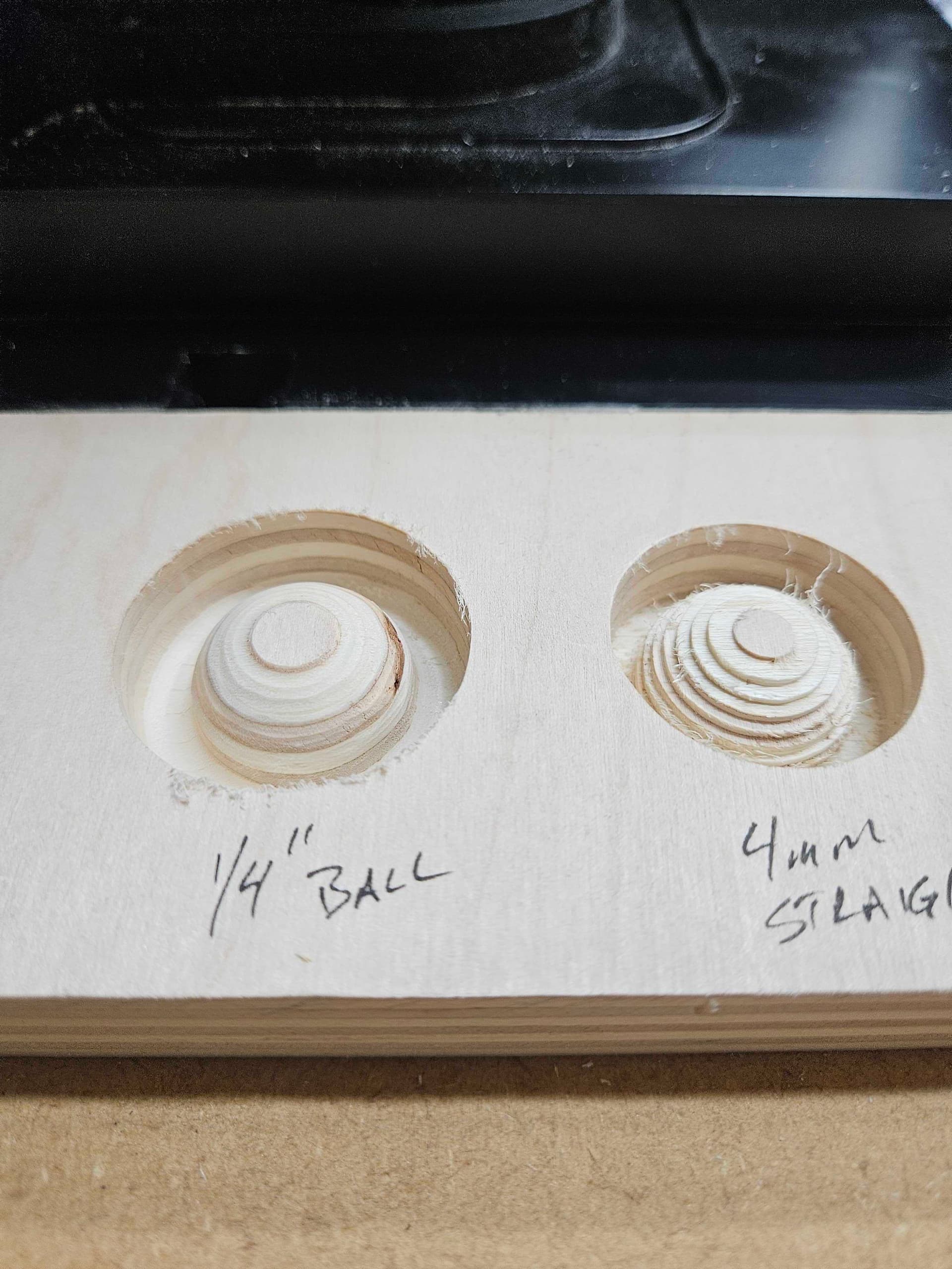
let me know when you cut your first thing using KM output. I looked at the ShaperTool many years ago and may still get one when I get a new shop setup.
The only other thing right now is with the custom cut type tag in there the "fill=“none” stroke=“black” stroke-width=“0.1mm” isn’t needed and ends up overriding that custom cut type tag. Not a big deal to find and replace with a space though.
Mostly testing since this isn’t really a 3d kind of machine so I am still trying to wrap my head around this new aspect of it.