Hello,
I am trying improve a part printed on a FDM printer with PLA, that looks kinda like a hockey puck that gets dropped a lot so the outer side cops a lot of the damage.
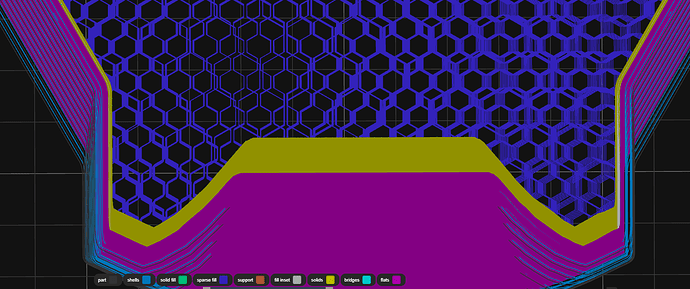
To make the part last longer I want to internally drop its weight by lowering the infill density internally in the centre but also re-enforce the internal infill around the edges where the damage happens.
For SLA print versions of this part in the software I use to slice it, I hollow the part, then add the infill, then manually add more supports inside the print. This causes the part to come out at a fraction of the weight which in turn less damage to it’s self when dropped, but I have found other issues with the resins over time. So I am going back to see if I can get improvements FDM/PLA version.
One advantage of why I want to try improving a FDM version of the part, is that after printing I coat the part with resins (from my SLA machine) that soaks in well and re-enforces the part. This also allows me to use flexible resin around the edges that take the impact and harder resins the faces. This works well as I get the benefits of PLA and Resin.
I can edit the part but I would prefer to do it in the slicing process or post print if possible.
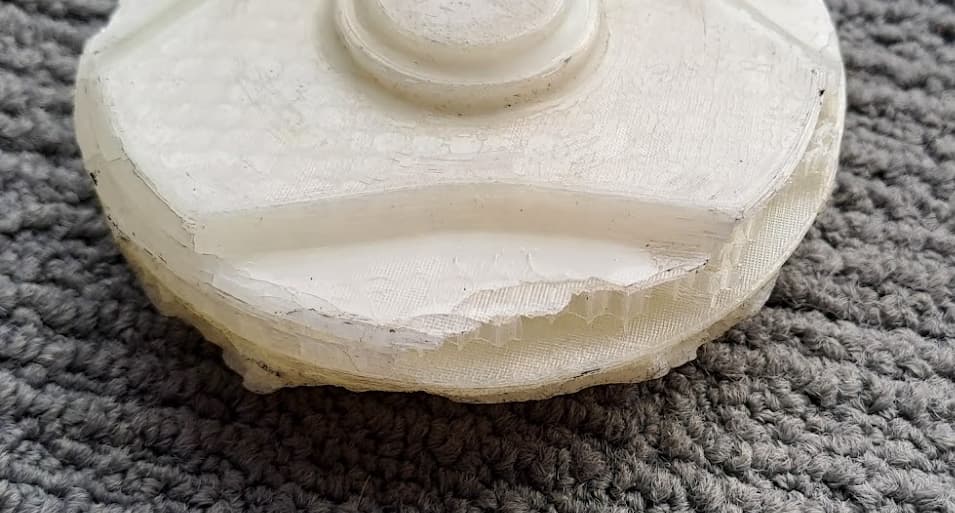
This is a photo of one of the damaged parts printed in PLA with Anycubic UV Tough resin coating.

