Here’s another wrinkle 
And the writeup got long 
While trying to work up simple examples for depth-first path order issues, I blundered into another category of trouble: step-overs > 50% can leave uncut material, possibly in significant amounts. Some cases have simple solutions. At first glance, it looks like a general solution will multiply the computing task. Surely someone else has figured this out but I didn’t quickly find the answer. I did find some stuff to maybe read some day.
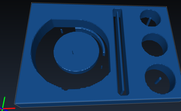
This bunch of pockets roughed with 85% stepover shows a few ways material can get left behind. Simulated in CAMotics.
1 of 3
This shows the toolpath that left the curved wall between the round island and the pocket side:
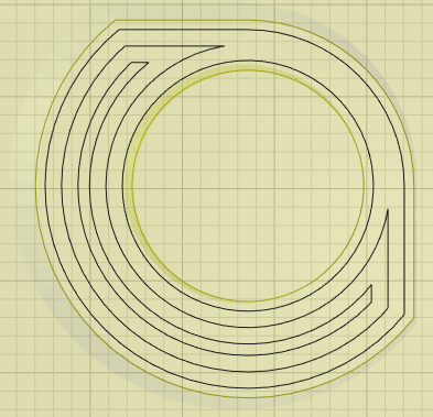
The slicer left two paths more than a tool diameter apart around the upper-right quadrant of the island. These are two separate loops - one offset outward from the island and one offset inward from the pocket wall. It looks like the algorithm offsets both, detects their collision, concludes there is no room/need for two more paths through that area and considers it done.
Easy answer?
I think it looks like this can be solved by trying one offset path at this point before concluding that the two series of offsets have met. When stepover exceeds 50%.
This is not a contrived example. It’s simplified from this miss that got me started down this rabbit hole:

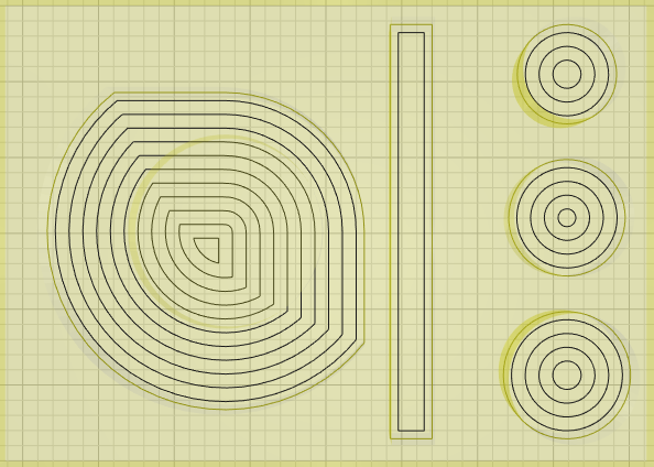
This sliced layer shows the rest of the hazards in the simulated example above.
2 of 3
The long wall in the rectangular pocket and the spikes in the centers of the island and two of the round pockets all show a series of single loops offsetting inward until no further full stepover offset is possible.
Easy answer?
I think it looks like this can be solved by trying a 50% offset inside the last fully offset loop. When stepover exceeds 50%.
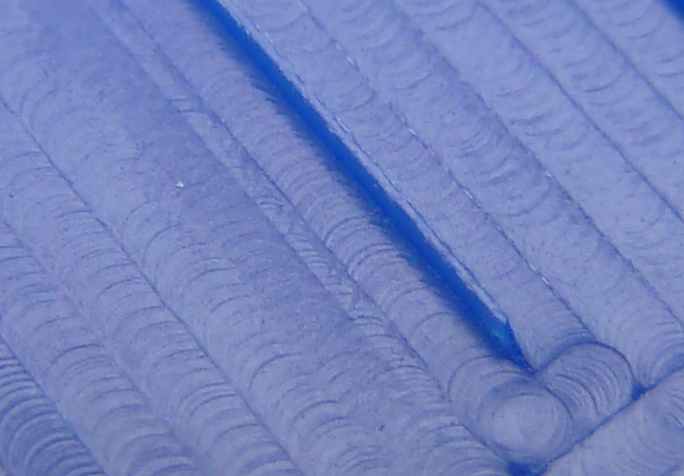
This is not a contrived example. When I saw the ridge below I chalked it up to tool deflection while testing fast(er) feeds & conventional milling at 80% stepover. It seemed inexplicably regular for an irregularity, but I didn’t let that bother me at the time…
3 of 3
The two spikes off the ends of the curved remainder happened between successive offsets in the same series where offsetting inside sharp corners makes the path corners too far apart. And I just noticed the uncut corners between the innermost and next rectangle in the photo above – I recall fuzz in that area remaining attached so that it had to be scrubbed vs. simply vacuumed away.
Easy answer?
Um, so far that looks like a No. For a general solution. Within the world of offset parallel paths. But I couldn’t help thinking about it…
A brute force general solution could be “simple” in principle but costly in execution:
- Generate the next full (>50%) offsets
- Generate 50% offsets – which represent the edge of material cut already
- Generate 50% offsets back from the new full offsets – which represent the edge of material to cut next
- Test for gaps between the two 50% offsets
-
- (100% stepover will complicate this - maybe filter for minimum width across a gap?)
- Fix gaps
-
- Robustly: Use the outline of each gap as a new path loop that won’t hit anything it shouldn’t and will hit everything it should
-
- Likely sufficient:
-
-
- identify the near “corner” of the new offset (ideally, the offsetting code will have retained knowledge of discontinuous corners)
-
-
-
- Identify the point on the perimeter of the gap farthest from the “corner” of the new offset
-
-
-
- At the “corner”, insert into the new offset path an out-and-back spur in the direction of the far point of the gap, stopping short by a tool radius.
-
That triples the number of offsets to generate and adds more area intersection tests. I don’t know how much that would add to total processing time. Or how tedious that would make the toolpaths.
More practically, it seems like many/most corner misses like this will happen in simple sharpish corners between straightish segments. Assuming that condition should allow some heuristic to greatly reduce the compute load. I assume the offsetting code knows when it generates a discontinuous corner. I don’t know if it already exposes that info. Those points mark where to look for the possibility of missed material. It seems like doing that should be easy but every time I try to write up a “simple” process I end up with more conditions & edge cases than I feel like writing about.
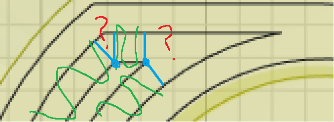
The scribble below says most of what I haven’t discarded from thinking about this. Blue marks the discontinuous corners that (I think) the offsetting code could flag, and two perpendiculars from each corner. Green squiggles mark well defined path segments and cut areas. Red marks the areas that seem like they should be easy to approximate and determine either than they are clear or how to clear them.
This seems to describe something in the ballpark but I haven’t read it:
Toolpath Optimization on Automatic Removal Uncut and Application
Perhaps much more practically, one could use knowledge of part geometry to figure a maximum safe stepover. For example: when clearing inside 90deg square corners, limiting stepover to 70% (2^-0.5) ensures complete coverage. Tighter corners reduce safe stepover; more open corners increase safe stepover. 100% stepover clears completely only where radii never get any tighter than a tool diameter until the inner-most loop - which maybe means circles and sausages with parallel sides and half-circle ends?
Stuff to read:
Maybe. Some day.
This 2016 thesis is paywalled, but the substantial excerpt includes most of a recent literature review.
Pocket Decomposition using DN and HARI Number. A Novel Approach
Also paywalled, but sounds relevant: “The 2D-curve offsetting solution has been widely studied […] However, though the tool-path linking may seriously affect the machining performance, there have been few reported investigations on optimizing the CPO tool-path linking.” 2002.
Offset tool-path linking for pocket machining
Potentially confusing:
Dude says CPO. “The literature” speaks of contour-parallel offset and direction-parallel offset. It appears that lettered people uses “contour” to mean something more like what KM labels “outline” than like what KM labels “contour”.