Thanks for the great tool. I am finally starting to get the hang of this a bit more but an issue i cant seem to figure out. I am trying to use trace feature to cut a simple grid/lines into my CNC router waste board. But the slicing never completes and not sure what I am missing. Essentially a few vertical and horizontal lines in inkscape. Import into kiri and scale to 0.5 mm Z only. This will get carved out of the “stock” defined in Kiri and not any object/part (I assume this should work).
Trace / follow lines with no offset. + to add and select bottom edge (lowest Z) of imported scaled piece and trace/check to complete selecting edges, click Preview (or animate). it says “Slicing” at the top, but it never finishes. Even if I only select 1 “line”. I’ve waited 10+ minutes on both Firefox and Chromium. I’ve reduced the number of lines and just selected 1, and played for a bit with no luck. Won’t let me attach my workspace as a new user.
Inkscape doc 200x200, grid 2 vertical 2 horizontal lines 199x199 (“smaller” to avoid issues for process of elimination)
stock 200x200
Limits Z-Anchor top
z-thru (0)
origin top
import
scale to 0.5 mm
trace - 1/16" endmill
lines/follow/none
step down 0.5 # to match scale i.e. depth
cut through 0 # don’t need any extra
select bottom of 1 line (vertical)
Check
preview (never finishes)
One thought was setting Cut through 0 and Z-Through 0 . I was trying to just have it cut the exact height of the trace part depth.
Hm the more I think about this, the more I think the slicer may need an actual 3D “object” to slice and it can’t be a path out of raw stock?
I was trying to avoid that so I could essentially do say a cutout in whatever/wherever without having to combine to 3D models in modelling software first . ( a positive and a negative exclusion by a difference). Was hoping I could just just center the inlay wherever I want it to go and set the stock to large enough and cut away to a depth. If I can generate paths out of raw stock I could stack jobs and be more flexible. I.e. 1) cut the part with first model and cut 10 of them the same way 2) cut an ACORN inlay into part 1 a shield inlay into part 2 etc… But If I have to combine the parts with the inlays I have to create 10 3D designs. I don’t know I am still learning.
Update. So if I try to use the trace as a dressup out of raw stock with an inlay part it seems to work fine to slice/preview at least (haven’t tried actually cutting). So it must be something with the vertical lines thing. I.e. import a shape (i.e. circle) and loops/clear.
BTW incidentally there seems to be some kind of a bug I can’t quite naildown. But the “offset” seems to only sometimes be available on loops/clear. Something to do with switching between loops clear and lines offsets. At least that’s what it looks like.
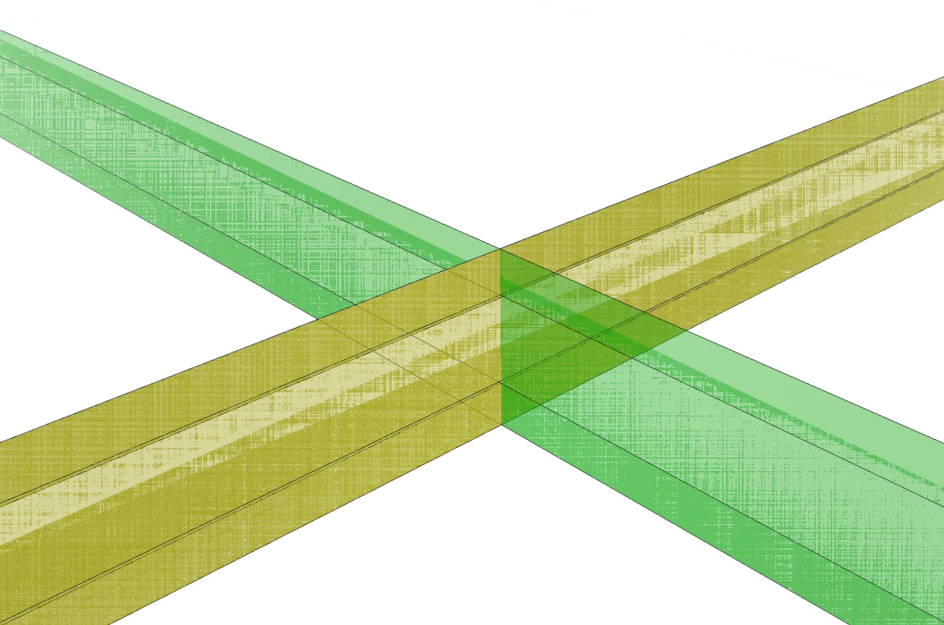
Got it. The imported object / mesh appears to be a set of grid lines with no “width” in the X or Y (depending on orientation), so their “shadow” projected onto the platform is invalid. This is causing an error (which you can see on the javascript console) and preventing slicing from completing. This isn’t an anticipated use case with the current code.
Is the goal to have the endmill just follow those lines? If so, the best way to achieve that is with a 3d model that has “V” grooves where you want the lines then trace the center of those. Couple that with a flip operation so you can process X and Y lines separately. If you cross the lines, it’s harder to select.
Attached is a workspace that demonstrates this. Basically you export the gcode for one axis, flip using the flip op and export the gcode for the other axis.
Yes the goal is just to follow the lines. It’s odd they had no width since I set a stoke width in inkscape. I had already created a workaround model very similar to yours. Though I confess I am not sure how to do a v-groove that easily I used rectangles and was just gonna select once “side” of the groove to follow. Same deal I think.
I just personally think its clunky to have to define a whole 3D model and flips for what is essentially a surface operation. I.e. carve a sign out of a piece of board. This has always confused me why I have to fully model the entire sign. Define a 2D structure (letters and a border) and the tool can set the scale (Depth) and done carve it.
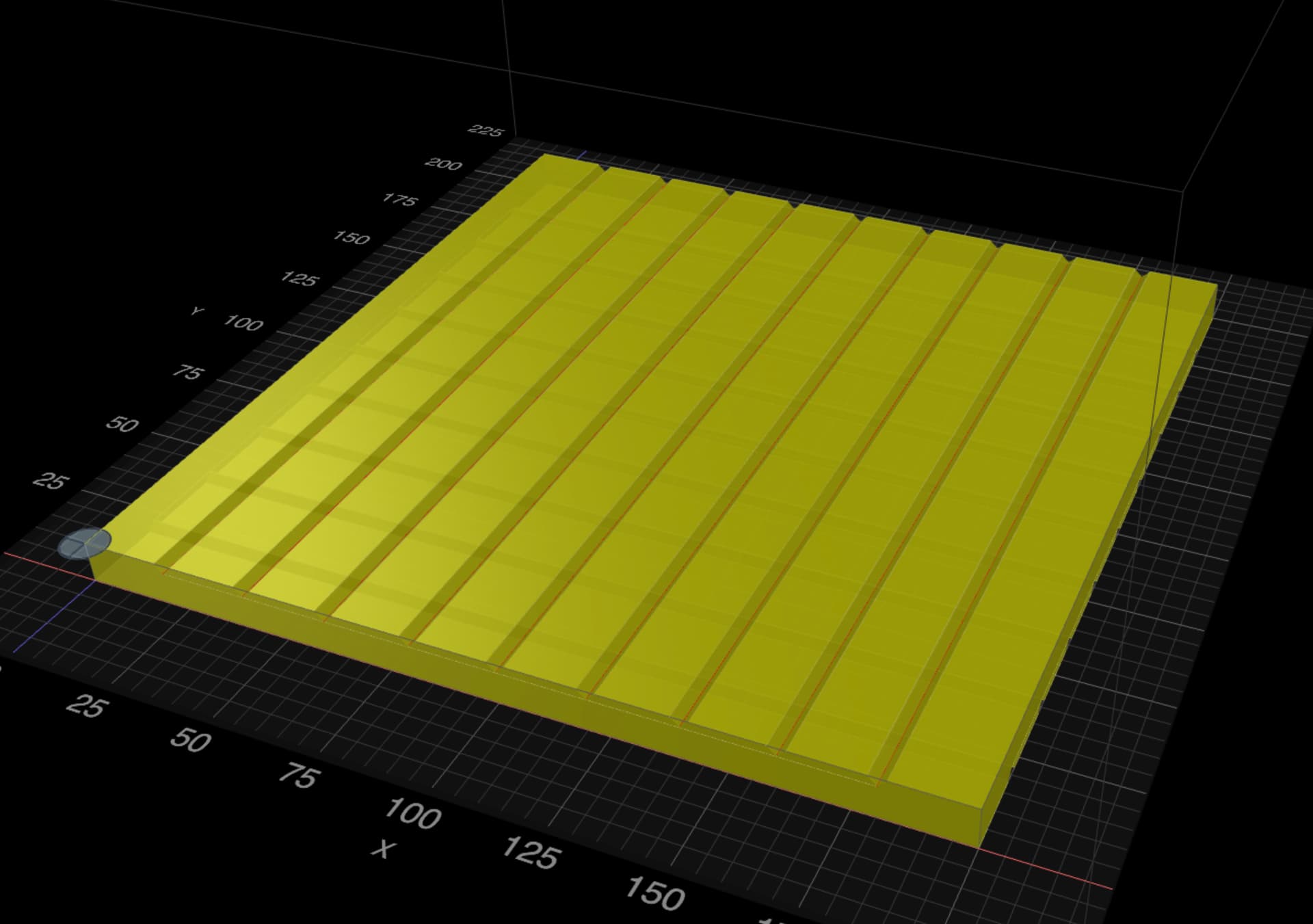
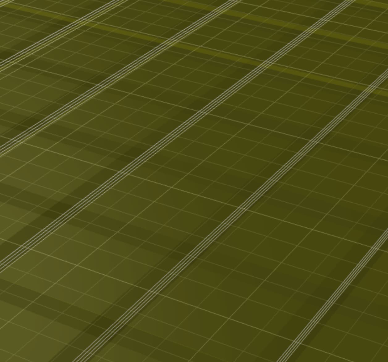
Based on your info I went back to my original design and changed it to be filled rectangle lines instead of a single line. Then when I imported and traced I just selected one side of the rectangle to follow (one side of the trough) and that seems to work. I am able to slice and the animate shows the desired behavior. Seems to work.