I am working on creating a simple spoil board. I have a ball nose 1/8 end mill cutting a grid 1/8 deep. I set my material to the same dimensions as my board and model, 53" in the x 48" in the Y. I am not sure the best tool path to create or if there is a better way to model the grid maybe? When I go to kirimoto to generate tool path, it tells me my x is to small. If I set x to 53.001 it will generate but also cuts the edge which I do not need.
This is my first project and it is all new to me. Any help is appreciated.
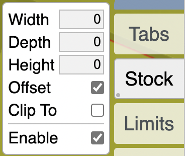
hi @muellercandd and welcome. first on the stock, just set it to offset and 0,0,0 and it will be the same size as your model.
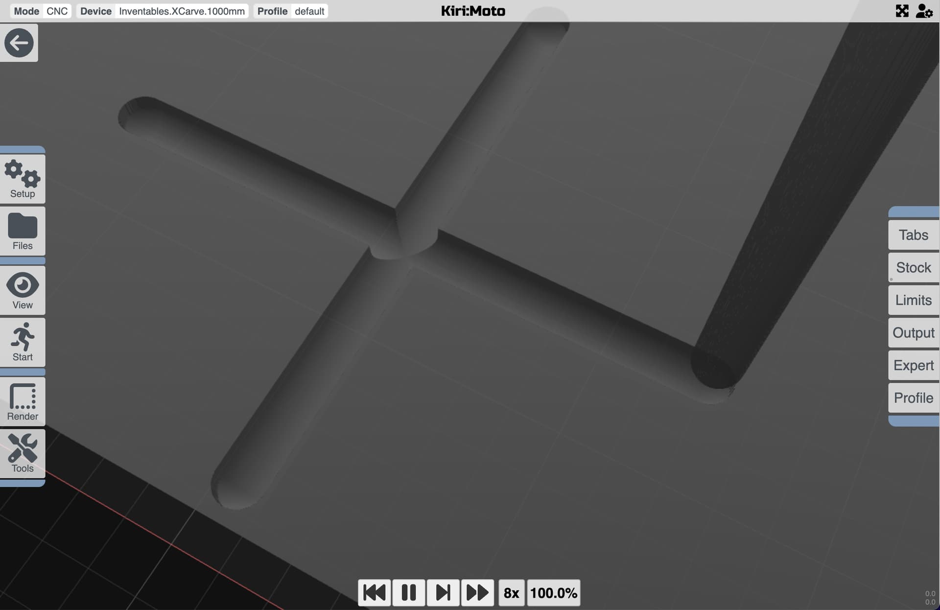
as for the model, it’s really hard for the engine to detect contoured pockets the same dimensions as the end mill. it’s better to model the grooves as a V shape, then use the trace tool to select lines.
this is your model close up using a pocket tool to highlight the cutout areas
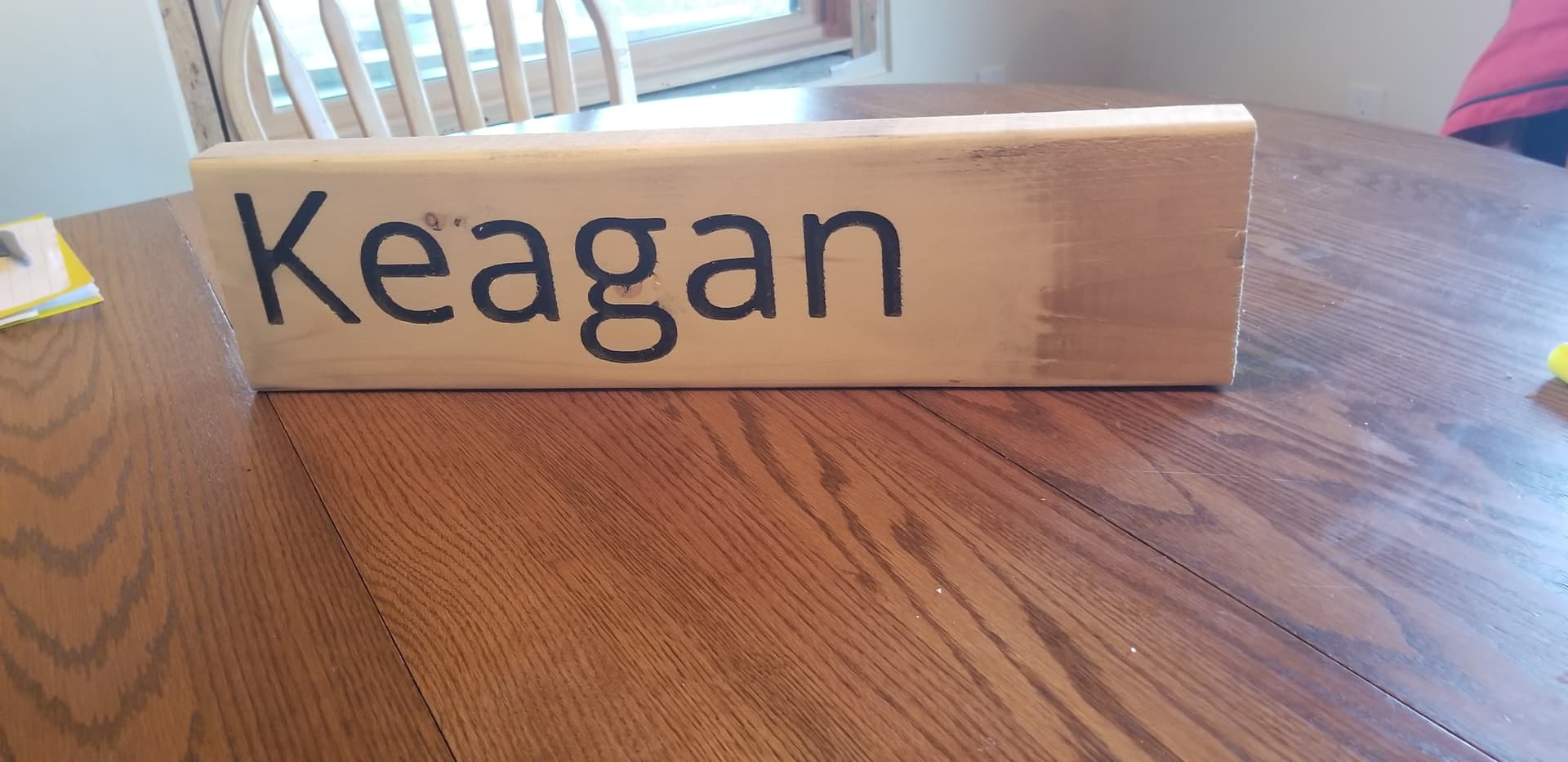
Oh boy, I made my spoil board. some hickyos on the way, but i got it!! Now, I stafted a simple project with just text on a board, only need to cut out the inside of the letters. I used conture and am not happy with the result or time to cut. Trace will not work in this case. Any suggestions? I coukd do conture again with a smaller bit?
Text is tough. If you can use pocket, that might do the trick. it has both contour and trace options. try those out. pics of the final animation and cuts always helpful.
Does anyone have a workflow for converting Onshape Text to a 3D V Notch? I would love to be able to just do a “Trace” like what was shown here so I can engrave single pass lettering but Im struggling to get a midline modeled off letters correctly. Any tips?
Hi @LukeMckn … the difficulty with turning arbitrary text into V engravings is the fact that not all lettering has a single, neat, identifiable mid-line. Font selection is the most important factor. Here, unfortunately, Onshape does not provide a very good selection.
A path forward might be to use a free SVG browser-based editor to create the text you want from a wider selection of fonts. Export that as SVG, convert to DXF, import the DXF into Onshape, then add that DXF inside a sketch.
I have been working somthing that has raised lettering and this is exactly what I did. Converted a word file to .dxf and added it the sketch. But these letters were extruded not carved. I came across a text editer, dont recall where that i think could turn text into a single line and then to dxf. Could it possible to have a function that let kirimoto folow the lines of a sketch on a surface? I have other dxf files that I extrudes but it would be great to just import and and follow the lines? I know so little about program wrighting that I am not even sure I am talking about something feasible.
Can you be more specific about how that work flow would work? It seems that would still leave me with a text outline instead of a planar linear path that Kiri moto could trace. Even if I extrude with a draft, which converges an outline to a line, I still cannot trace it well because the lines are not coplanar. Am I missing something?
The other issue is that even if I have a midline font (or just manually sketched the lettering, like @muellercandd said, it is only in the sketch and therefor cannot be followed in a trace. I would need to do some clunky modeling just to convert a line to a 3d object that comes to a line edge, subtract that from my surface then use the trace.
I will be adding a 2D path option that allows you to import sketches and have them directly followed by a tool. Targeting the 3.8 release. In the meantime, you’re correct that the trace function requires lines co-planar with Z. I could look into relaxing this requirement when selecting lines instead of loops.
Stewert, a 2d path oprion would be great! Will you need help testing?
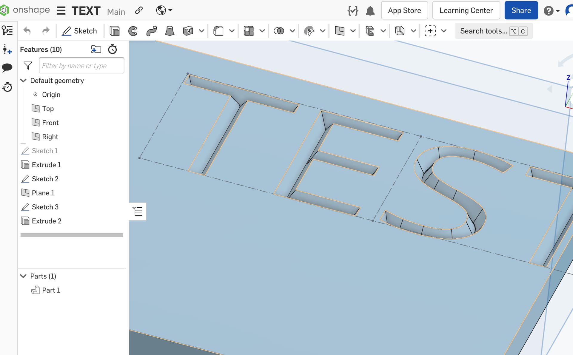
Luk, the questions you have were the same as I had. How I created mine was as follows:
Made text via text took,
Extruded a remove,
Placed in KiriMoto and selected pocket,
In pocket there is a drop down for line or curve (i think) select line, then the plus,
on your 3d part select the bottom flat of your letters and then generate
For me this created a tool path for just the carved letter. I used an endmill but if you wanted a Vbit, I would think you could choose an endmill that has the same od as your letter width and then just use the v bit? This would not work if if your letters very in width though. Stewatrs 2d trace would make a world of diffarance I wookd think
@stewart Thank you so much for the time and effort you put into this program! Im excited for the next version and until then I’ll try out @muellercandd methods!