Output for an Axiom CNC using RichAuto B11

Hi,
I’m expecting delivery of an Axiom Iconic series CNC. I’ve used OnShape to model for 3D printing and have experimented with KM in preparation for generating CNC toolpaths. However, since my machine isn’t listed under standard devices, I’m wondering how difficult it might be to modify one of the supported devices to generate suitable Gcode. I have a list of the supported g-code functions for the RichAuto controller and several examples of g-code files to help with formatting. I have compared a few files produced by KM (various machines) with the samples for the Axiom system, they don’t seem all that similar. As you can probably tell, I’m new to the CNC world but I’m pretty resourceful and don’t mind digging in a little bit if it will save some cash in software subscription fees…

thanks,
Brad

Hi Brad,

Can you drop a sample of the Axiom gcode here? Or an url to their gcode reference.

Thanks,
Stewart

Thanks Stewart,
I’ll copy some text I received from Chad at Axiom and attach the files he sent.

Thanks!
Brad

Chad says:
*Not all g-code functions will be used for our application, however, the RichAuto DSP supports the following codes.

G0, G1, G2, G3, G4, G40, G41, G42, G43, G44, G49, G54, G55, G56, G57, G58, G59, G80, G81, G82, G83, G84, G90, G91
M3, M4, M5, M6, M8, M9, M208, M210, M211, M350, M351

I’ve also attached the sample files, that will help them in formatting.

The big thing to remember is that while you can still design in inches, the code itself must be metric

Also:

The controller will accept a large number of formats automatically…s o it will not necessarily need to match identically. (The Kiri format is standard…with no line numbers, and the spacing…it will work just fine.)

The important details are that the properly recognized G & M codes are used…if a code is used that is not recognized, it may be ignored and the next code will be used that can cause a lot of problems.

And that the units are metric to ensure proper movement distnaces and speeds.

The F code is used…you will find it in the header portions of the file:

<

With Vectric, the speed does not change that frequently…

It appears that your software may be showing speed changes not just for cutting but also the rapid feed-rates for shuttle moves from point A to B…with our machines, the RichAuto controls shuttle speed independently (outside of the file or g-code).

That shuttle speed can be adjusted by the user before the file is ran if needed.

And in case you were going to ask…the S code (spindle speed) is NOT used. The spindle speed is user controlled at the machine, not through the code.
Here is some sample code from the .mmg file.

beginning…

(Filename: topi2r)
N10M03S18000
(3D Roughing 2)
N30G00X103.620Y-83.274Z6.350
N40G1Z-0.611F762.0
N50G1X-103.768Y-83.265F2540.0
N60G1X-104.834Y-83.178
N70G1X-106.182Y-83.018
N80G1X-107.688Y-82.767
N90G1X-109.203Y-82.441
N100G1X-110.722Y-82.037
N110G1X-112.237Y-81.554
N120G1X-113.748Y-80.989

ending in …

N770550G1X-106.115Y83.767
N770560G1X-105.781Y83.787
N770570G1X105.932
N770580G00Z6.350
N770590G00Z20.320
N770600M05
N770610M30
%

since it supports standard gcode, if you want to submit a device profile, I’ll incorporate it into the build and live version

I have this exact same problem right now. I have an Axiom 6 with a B18 controller and also need a post-processor. Has anyone solved this problem? I am new to kirimoto so I don’t know what a “device profile” is…Thanks in advance!

the only real difference between KM output and this sample file

1 - comments enclosed are in ( ) instead of prefixed with ;
2 - there are no spaces between tokens GnXnnYnnZnn (this is a KM output preference)
3 - lines are prefixed with Nxxx which appears to be a line number. I would expect the controller to work without these. if not, I can synthesize Nxxx line numbers as a device preference

the rest can be handled with gcode header/footer

Thank you for the reply Stewart! Unfortunately, I don’t know what to do with any of the information you listed. I only discovered KM this week and I have very little knowledge of how to deal with gcode. I have 2 engineering degrees (but not in this area) so I’m trainable, but I’m trying to avoid damaging my machine and/or breaking bits by experimenting with so little knowledge.

  1. Can I make KM change it’s comment delimiters to ()? or delete them automatically? Or does it matter?
  2. Can I make KM delete spaces between tokens (whatever those do…)
  3. So only a KM developer can tell KM to generate line numbers if my machine requires it?

I have no idea how to write a header/footer, or put commands into it to do what you say can be “handled”.

I’m trying to avoid spending thousands on a CAD/CAM software package like Aspire/fusion360 if I can make Onshape/KM work for free. I would rather spend my time making stuff than fussing with code every time I want to cut a project. I don’t mind a learning curve if I know i can eventually make it work for what I want to do. I have Vcarvepro, but I want to do more 3d carving (specifically making electric guitar parts). That’s why I’m trying to use Onshape since it seems easier to create 3d models in it than vcarve or aspire.

Sorry to be so dumb, but I was really hoping there would be a post-processor for my machine. I can’t be the first, or even second Axiom/Richauto owner to want this. Any help is greatly appreciated.

Jim

The approach I recommend is to:

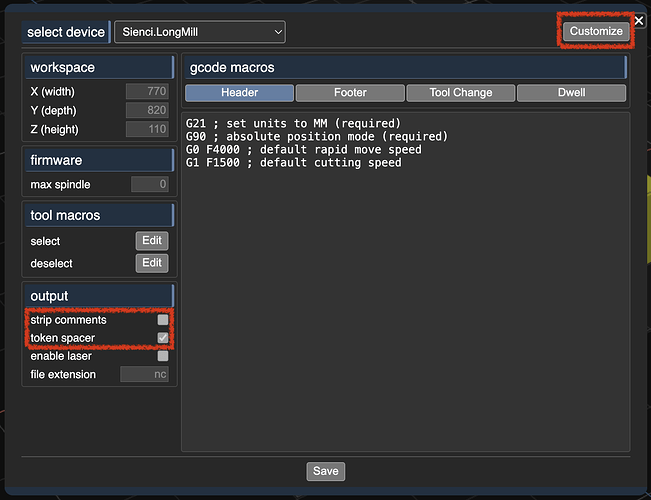
  1. “customize” some machine profile so you can edit device settings
  2. check/enable “strip comments”
  3. uncheck/disable “token spacer”

this should enable Kiri to produce gcode similar to the output above but without the Nxxx prefix. we can find out later if that’s important. You can always add a “%” to the “footer” tab if it turns out that’s important.

Next, I would create a very simple cutting profile. Let’s say a single pass around a square area. Use an outline or trace operation on a cube. That should produce very simple gcode.

Take that gcode to your mill. Home the Z to a point well above your cutting surface. You don’t even need a tool installed; we’re not going to cut anything. You just want to run a mock test to see if your machine will run Kiri’s gcode.

From there, once basic paths can be followed reasonably, you can move on to more complex tests up to cutting.

No one has ever needed line numbers, so that would be a new ask. But it’s also not hard to do.

ok this is perfect! thank you for being helpful and not treating me like an idiot (there’s too much of that in the world right now). I will try this today and report back.

2 Likes

I ran the file today a couple of different times at different z-zero points. It seems to have run fine, but it is clearly not subtracting out my “z-zeroing puck” height from the file. My zeroing puck is 25mm (or 098" according to my calipers). So when I run a file from vcarvepro, I zero with the puck and the file automatically assumes z=0 is 25mm below where the bit touched the top of the puck and runs everything from z=0 as the top of the material. So how do I make kirimoto do that with the output files? (so far I haven’t found any info on this)

Thanks,
Jim

How are you zeroing the Z axis?

Can you provide the gcode output from VCarvePro? We can look for any interesting commands that may be relevant.

I use the machine’s built-in zeroing procedure. There is no g-code for that that I can access. I don’t have to set anything in vcarve (that I’m aware of). Here’s how I zero:

  1. plug the touch puck into the machine. (25mm thick aluminum block with a wire and banana plug that plugs into the cnc gantry)
  2. Move the bit in the xy to a position over the puck (usually a couple of centimeters above the puck is fine)
  3. then I hit “tool set” on the controller
  4. The machine then slowly moves the bit down until it just touches the puck. (this completes an electrical loop which tells the machine to stop moving downward)
  5. Remove the puck and start the program.

Somewhere in the machine settings it knows the puck is 25mm thick and now sets the z=0 point to the top of the material which is the bottom of the puck.

This is standard procedure for z-zeroing for any cnc machine I’ve used or seen. Presumably, this is one of the things a post-processor that is machine specific takes into account. I have seen quite a few different zero-pucks of varying thicknesses used by various machines so maybe that’s part of it.

It is possible to force z=0 to where ever the bit currently is and some people put a piece of paper over their material and slowly move the bit down until it touches the paper to set zero. I’ve never done this as it seems unnecessarily risky with my bit if I hit the wrong button and it moves too fast suddenly.

Here is the first few lines of vcarve gcode from a job similar to the one I ran from KM:

(Filename: cutout)
N10M03S18000
(cutout)
N30G00X23.084Y60.844Z5.080
N40G1Z-1.465F304.8
N50G2X22.225Y69.850I46.766J9.006F8686.8
N60G2X23.084Y78.856I47.625J0.000
N70G2X61.017Y116.649I46.766J-9.006
N80G2X69.850Y117.475I8.833J-46.799
N90G2X78.683Y116.649I0.000J-47.625
N100G2X116.643Y78.714I-8.833J-46.799
N110G2X117.475Y69.850I-46.793J-8.864
N120G2X116.622Y60.877I-47.625J0.000
N130G2X78.858Y23.085I-46.772J8.973
N140G2X69.850Y22.225I-9.008J46.765
N150G2X61.017Y23.051I0.000J47.625
N160G2X23.084Y60.844I8.833J46.799
N170G1Z-2.931F304.8
N180G2X22.225Y69.850

This cuts out a circular part. I do notice that the circular cutting path is using the G2 command (circular interpolation, CW) where the KM code uses a G1 (linear interpolation) for a circular pocket. This doesn’t matter for the zeroing issue, but I’m wondering if it would affect the “circularity” of the feature if it is connecting points on the circle with lines instead of arcs.

I am going to double check this morning on the z-zero. I remembered I have some foam insulation I can use for material that won’t break a bit if it’s off calibrated. If KM is doing what I think though, it won’t even touch the foam. I’ll let you know.

Jim

I just confirmed that the KM code is completely ignoring the zero set on my machine. I set z=0 using the puck and the KM code cut as if the top of the puck was z=0 instead of the top of the material. Something is missing that tells my machine to use its zero in stead of the code’s zero. I don’t know what that could be…

do you have “origin top” checked? that sets zero to top of stock. if you uncheck that, then Z=0 will be the on the bed.

yes. origin top is checked. If it wasn’t my bit would be digging too low. It’s digging too high by the height of the puck.

please use files → export and send me the .kmz either here or email to [ sa at grid dot space ] if it’s sensitive. that way I can see how your workspace is setup. you can also email or drop the full vcarve gcode output so I can compare KM output side by side.

Nevermind. Right after I posted this problem on the Axiom discussion board, I realized I had not run a vcarve file to compare machine behavior to the kirimoto file. I was only comparing files. Lo and behold, the vcarve file had the same carving z-zero error. I checked the puck thickness in the machine controller and sure enough it had been set to 0 somehow instead of 25mm. Problem solved, but I don’t know how it happened. I didn’t even know where that setting was until today, and never changed it. Weird.

Sorry to send you on a wild goose chase when the problem was buried in my machine firmware. Just goes to show that if you can’t find the problem where you are looking, you’re probably looking in the wrong place… I still feel dumb for not realizing earlier.

I am now optimistic that KM will be able to do the types of carves I want. I appreciate the help and fast response.

Regards,
Jim

1 Like

Great to hear. Thanks for the update.