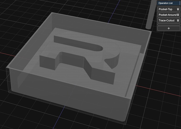
Outline and pocket with toolchange on inverted letter

I’m trying to create a metal letter stamp, so I want to leave the letter untouched and mill out all the surrounding metal, but leave a block of metal underneath.

In order to do this, my plan is to first do an outline with a small bit so that I can get all the fine details of the letter correct, and then continue with a pocket on the surrounding areas with a bigger bit to save a lot of time.

I’ve been doing a lot of research on how to approach this in KM, because almost all examples are of designs being milled out themselves, instead of an inverted milling operation like this. So far, I’m not sure if I’m missing something, but I’m stuck trying to get this to work, so I would like to ask the experts here!

I created an STL where the letter rests on a block, because it seems like the pocket operation needs actual design surfaces to indicate where to mill to (which makes sense). This works fine for the second step of the operation, because with a negative expand I can perfectly indicate that the bigger bit should mill out everything, but skip the first pass that should be done with the smaller bit.

But with this block STL the outline operation cannot work, because the whole block is seen as the outline. I also have an STL with just the letter R, which of course makes the outline work, but now the pocket operation is no longer possible because I cannot indicate where to mill the surrounding metal to.

Ideally I would like to do this in one single job for the machine, because I’m afraid that if I create two separate gcode files with different STLs as their basis, it will create some small offset or something.

Because I can only embed a single image, I’ve included an example of the block STL. The single R STL looks the same without the block underneath. If needed, I can also upload the workspaces themselves. Thank you so much for taking the time to read all of this, and trying to help me get this working, I really appreciate it!
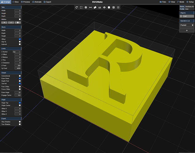
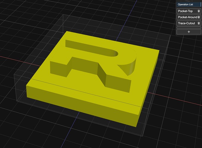
I’m not sure I 100% follow where it’s not working for you. Have you looked at the trace operation? I’m attaching a workspace that simulates your R stamp with three operations:

  1. R top pocket with slight expand
  2. R around pocket with slight expand
  3. trace cutout

If you want to test this, load it into a private browsing session so it doesn’t overwrite your settings.

r-stamp-workspace.kmz (191.3 KB)

Thanks for your response :smile: I’ll try to see if I can make my problem more clear, because the solution you propose indeed doesn’t solve it.

Looking at my image, I would like to first do an outline operation on just the letter R until the top of the underlying block, with a 0.5mm end bit. Then, I want to do a toolswap with a 2.5mm end bit, and mill out the rest of the space around the letter R.

The block underneath is just to give the stamp body, and is the entire stock, so it basically serves as the maximum depth all operations need to go to.

I hope this makes the situation more clear, if not, I will gladly answer any questions!

here is another take in 3 steps:

  1. small bit outline the R
  2. larger bit clear top of stock
  3. same large bit clear top of R (optional)

r-cutout-v2.kmz (248.2 KB)

It’s typical to rough out first, then come back for the finish pass later. Why do you want to use the more fragile 0.5mm bit first?

I’m guessing it’s because the pocket operation does not offer a leave stock option. but now that I think about it, rough with inside only would do this. so here is another version in only two operations that starts with the larger bit. also, just noticed the trace in the last one I posted had an error.

r-cutout-v3.kmz (254.0 KB)

Thanks @stewart and @mcdanlj, this is indeed exactly what I wanted to achieve!

I’m still getting familiar with cnc as a whole, so I didn’t realize that I could apply a rough operation here as well. Now that I think of it, it makes so much sense, I’m not sure why I didn’t realize this myself. You’ve both made my day, thank you so much :smiley:

2 Likes

Since you are new to CNC, I’ll ask: What machine do you have, what kind of metal are you planning to cut, and what kind of 0.5mm end mill were you planning to use? Do you know how to calculate speeds and feeds for it?

@mcdanlj The machine is an Eleksmaker EleksMill, so yeah, very much low-end. I got it gifted by someone who bought it in a spur, but didn’t know what to do with it. And since I’ve been using and tinkering with 3D printers for years, he thought I could use it. So far I only worked with wood and simple contouring, but this time I have an actual project on which I could really use this letter stamp that I intend to make.

My endgoal material for this project is brass, but because I didn’t want to start with that, I thought of using something a little bit softer (and also cheaper), so my ‘test’ material is aluminium.

I bought three solid carbide micro drill end bits (0.5, 1.5 and 2.5mm) for non-ferro metals. I wanted to start my testing with the 2.5mm bit, and work my way down. But I fully expect the 0.5mm is maybe above my skill grade, and is something I will have to let go in favor of the 1.5mm one. But I’m fine with testing (and maybe breaking, with safety goggles on!) the bits so I have an understanding of what I can do with them.

Regarding the speed and feed rates, I haven’t looked into a way for calculating them. Up until now I saw and read some mentions about it being a ‘test and calibrate’ way of finding the exact numbers, depending very much on the material and the machine. So I wanted to start with very low numbers for both of them, hoping to strain the machine and bits as little as possible, whilst keeping them lubricated, and again work my way up to a number I’m comfortable with, but still well within the capabilities of the machine and the drill bits. But your question has triggered me into looking ways for calculating this anyway.

Although my experience with 3D printers really helped me getting this low-budget (with almost no documentation) machine up and running, I’m still learning a lot, which I definitely like. So again, you guys helping here is great.

1 Like

Aluminum and brass are very different. Aluminum cuts nicely with very sharp tooling with lots of rake angle to clear the chips away from the cut. Brass “grabs” and a tool with lots of rake angle will break almost instantly. Aluminum likes 2-flute and “0-flute” end mills; 3-flute and 4-flute tend to pack up with chips. It’s not about whether it’s soft or hard; they just have different properties when cut.

The smaller the bit, the more you care about rigidity of your tool, because a small amount of deflection is still a large amount relative to the size of the tool. High-speed steel end mills can flex a little bit, but carbide snaps easily. Similarly, the smaller the end mill, the more runout matters. Runout is deviation from axial concentricity between your spindle and your end mill.

I have a large benchtop (manual) mill that is quite stiff and heavy, and I work gingerly with a 2mm end mill.

You might consider starting by milling machinable wax and then casting your letters. For work of this size, this is a common pattern. You can learn with pewter or other low-temperature alloys before moving up to brass casting. (Be aware that brass gives off poisonous zinc fumes when melted; this is definitely an outdoor activity.)

The EleksMill, as far as I know, is really intended for wood and plastics.

2 Likes

So much useful information, thanks a lot! It’s clear I’m just dipping my toes in the world of CNC and have a lot to learn, which is exciting. I will definitely dive into all the topics you mention.

Your suggestion of doing it by casting into a wax mold is something I also thought of earlier. But dismissed it because I didn’t want to add yet another technique I’m unfamiliar with and would have to figure out how to do. The funny thing is, this all started because I wanted to add a small detail to a big project I’m working on, but all this completely sidetracked that and the focus on that small detail is taking longer than the entire big project took up until now, hahaha.

Given what you are telling me, I will have to rethink my strategy, but I have gained a lot of new routes to explore. Again, thanks for the (safety) advice, really appreciate it.

2 Likes

Ah yes, when the side projects to make the side projects get side projects of their own… :smiling_face:

1 Like

For context on those tiny carbide end mills, This video shows how fragile they are. Most of us don’t have a scanning electronic microscope handy to debug breaking tools!