First of all, incredible work on the Grid.Space projects!
(I have some supporting images that I can’t upload as a new user)
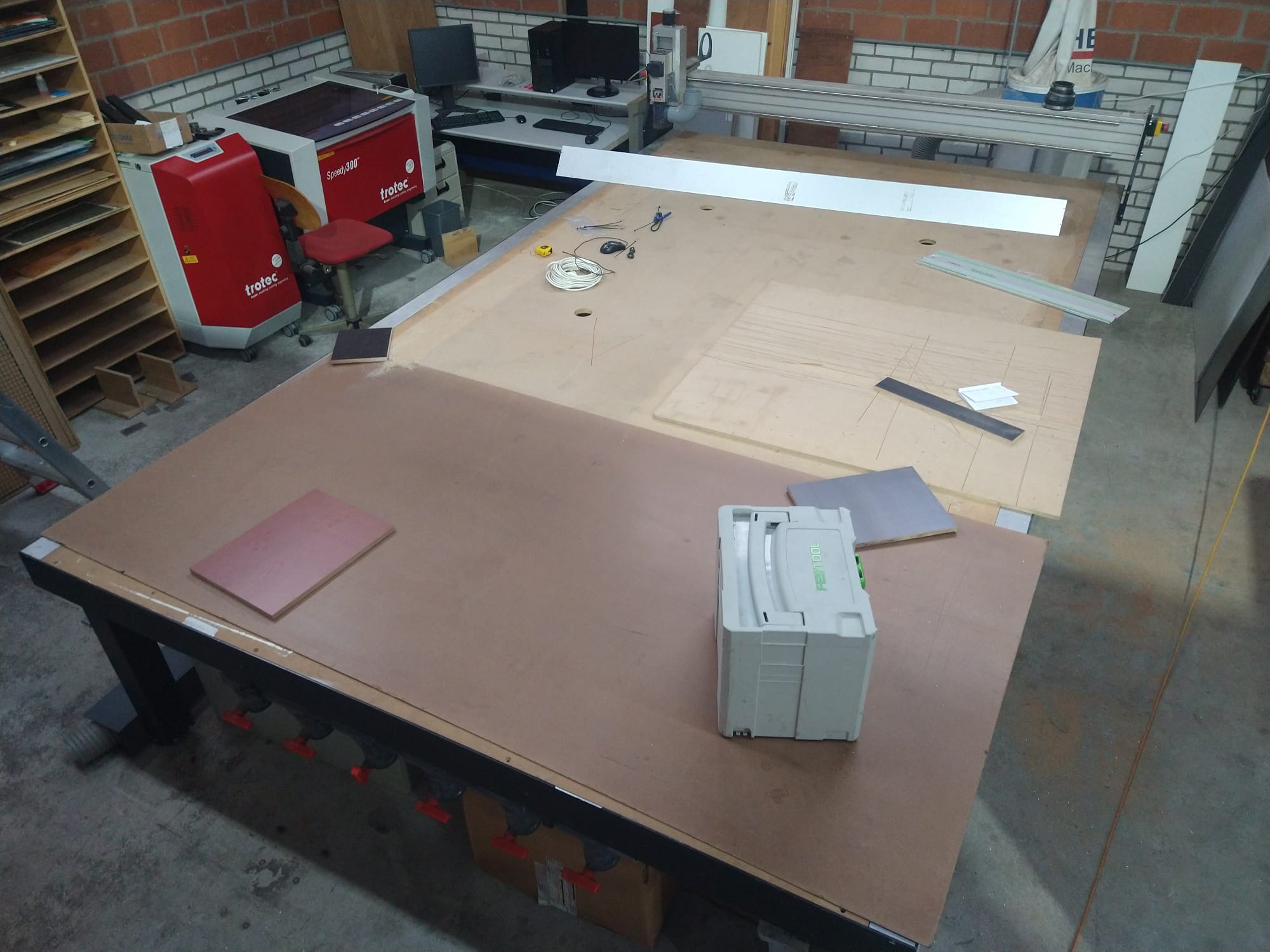
I am trying to create a custom sewing dress form from foam. I already modelled it in CAD and I was planning on cutting it as a stack on a lasercutter, this is how I found Grid.Space. Sadly this will need a lot of post processing afterwards to make the form smooth.
(missing image)
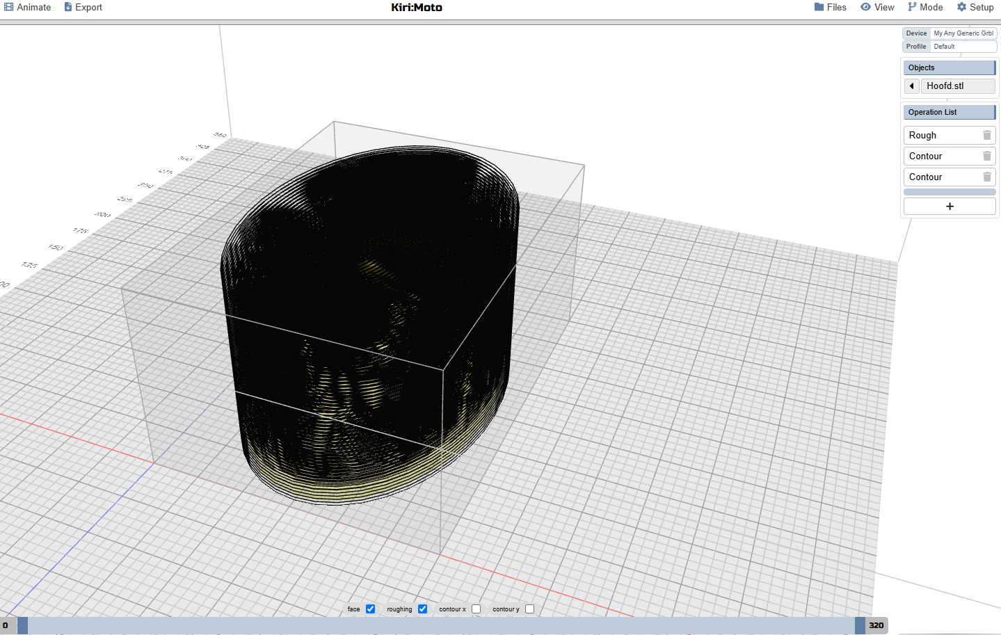
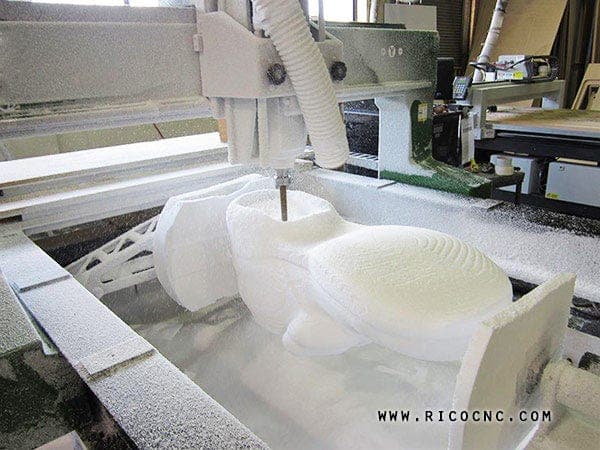
But then I discovered you also have created a CAM package and we do have a router that would be able to mill the shape:
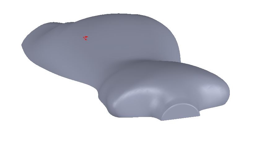
I would cut the dress form in two and mill the two halves separately. There is only one issue, the widest point of the dress form is not in the same plane and therefore there are some slight undercut areas (best visible at the shoulders):
(missing image)
Yes, with a straight ball nose you would get 95% there and it is a lot less work than finishing the lasercut stack, but is there a way to use a lollipop mill that could potentially undercut the shape even further?
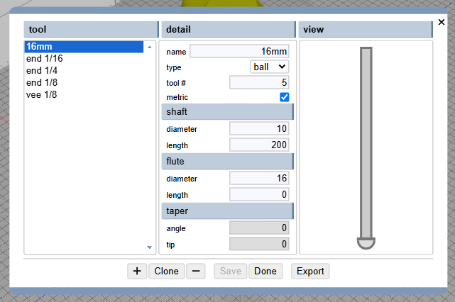
I can get close with the shape of the mill but I’m not even sure this would create undercutting paths:
(missing image, mill looks something like this: ====D and yeah I know)
Again, great work on open sourcing these CAM products, I wish I could program!
if you can find a perimeter line or some edge coplanar with Z (you could add this tiny feature to your model just as a tool path hint), then you can use the trace operation to select it. trace allows arbitrary offset distances. so in theory that gives you your undercut path. the only problem is you need a lead-in to the path instead of coming straight down to it for the undercut. this was recently requested and I’m trying to come up with the best way of implementing it.
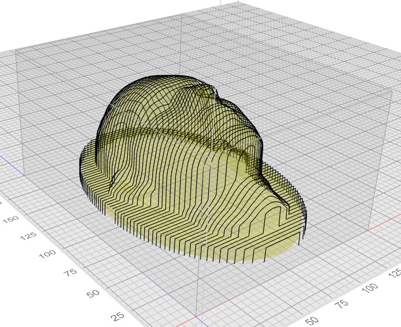
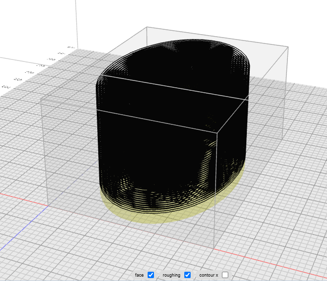
Okay, so I believe I can upload images three days later, here is the example of the dress form if I were to lasercut it in layers, the end result would be very rough:
But especially under the shoulders there are undercuts that could be milled with a lollipop bit. But there are no perimeter lines that I could use, it would be lovely if the contour option would follow undercuts. This is also how far I came to creating a lollipop bit:
I will be experimenting some more and I will try to do some air milling (or what the term might be) to test if I can get the gCode compatible with my machine today. Thanks for the quick response on my last message!
on the last one, does the operation have “inside only” checked?
as for the rest, it is computationally possible to do lollipop with auto undercut in contouring mode. I’ll have to think about it, though. it’s a fair bit more involved to code up.
And for the undercutting, it would be nice but I expect not too much cleanup from it anyway and I don’t know how many people would find this feature handy. It only helps with models with undercut but not too much undercutt.
For the air-cutting test however the machine performed well, making our machine possible a lot more versatile. Thanks for the development!
I misunderstood about “clear out all the stock” … I thought you meant the outline of the oval which is cut in your updated picture, but not the one above. There is no option to clear all stock. you would have to add a thin base to the model to achieve that.
Bystander here, wondering if your machine has enough vertical clearance cut the form as a single two-sided part.
Or if not, possibly you could slice it into three parts: front & back parts with no undercut, and a middle section to cut from both sides. ?.
Yeah, I am weighing my options right now. the machine has a 200mm clearance and Z-movement, so theoretically I can go up to 100mm with a 100mm cutter. But I can remove one of the MDF panels and use more depth in between the rafters, getting 200mm depth in order to mill two halves and put them together (which was my initial plan).
Right now I am leaning towards splitting the model up, either with a bit of post processing without flipping the center part(s) or flipping it like you suggest since this center part would have two flat sides and can have locating holes. Still undecided.
The last possibility would be the absolute coolest and that is to have a rotating axis on the bed in between the rafters, this would allow to create this form (and possibly more if there is interest) without glue-up, undercut, etc:
Just spit roast it and have at it. But right now I have too little CAM experience to tackle that yet and I don’t think there is any software like grid:space that would allow me to do this. My controller has a 4th axis so in theory that would be possible and would allow easy manufacturing of custom dress forms.
Right now I am leaning towards your suggestion with the limited clearance, with or without flipping the part.
Sounds like you have a good start at generating options and working out a process that will work for you.
I’m puzzled by your comment about “up to 100 mm” thickness with 200mm Z clearance and travel. Did you mean 100mm is your longest endmill? With sloping sides all around your part thickness is not strictly limited by tool length.
My gantry is about 100mm above the workspace, but this is also the max height of the toolhead (which is quite big, especially with the shopvac connected to it).
So if I have a 100mm tool I have 100mm clearance left.
If I have a 200mm tool I have 0 clearance left.
With a 50mm tool I can in theory machine from 0-150mm but I have to make sure the toolhead doesn’t collide with the part, so I’d rather be on the safe side, especially since I have very little experience in CAM.
That sounds very interesting! I haven’t found yet where I can add a 4th axis in Kri:Moto but I’ll first start with the basics anyway before building a 4th axis. Good to know that it is supported though, if I can find the setting I might start to play around with it!