You’re really punching out the updates here!
Regarding D7:
Non-depth-first roughing is looking good. Particularly the consistent perimeter outlines.
Path ordering for depth-first outlining is looking good.
And then there’s some other stuff.
CAM output
Roughing:
-
Request: I’d still like an option to double the outermost contour in roughing ops. Also inside voids when “clear voids” not selected. Like “wide cutout” except might not be cutout if tabs or not full depth or through.
-
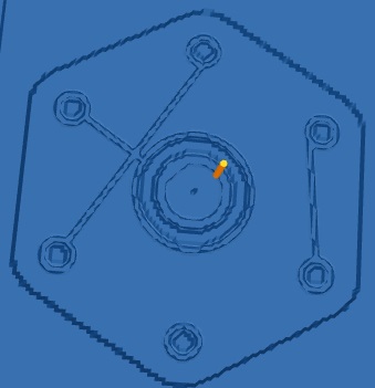
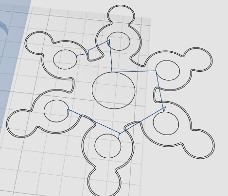
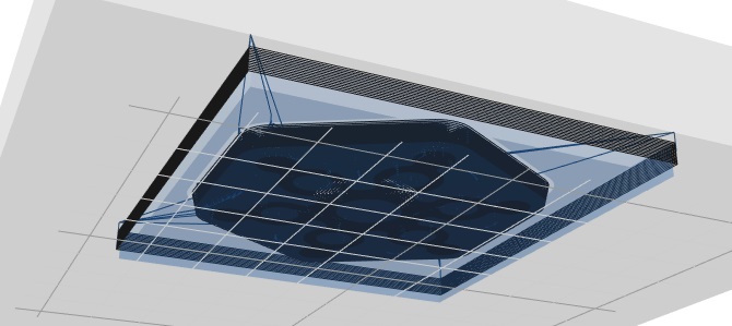
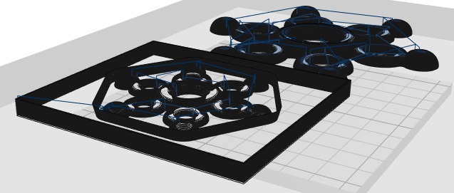
When “clear voids” not selected, roughing generates triple (two extra) outlines inside voids. Pic shows bottom slice of part on right - part is not in a pocket.
??as if intended to double perimeter outlines but second outer perimeter come out as third inner perimeters instead??
(ghost part not rendered, but ghost part to left is - more about that below) -
Depth-first roughing appears to generate only layer-by-layer output – with duplication – and less orderly final toolpaths than non-depth-first roughing. Depth-first generates larger gcode files that include irregular sequencing.
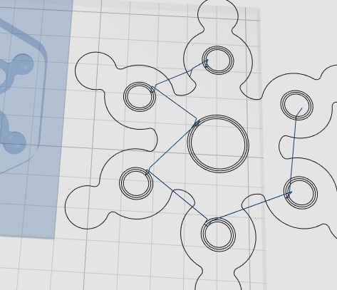
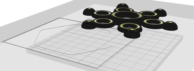
Moves that didn’t drag through uncut material were moves across the center. Reviewing this sequence: 1) bottom small circle, cross center to 2) top, drag to 3) bottom left, cross center to 4) top right, drag to 5) bottom right, cross center to 6) top right, drag to 7) single loop around center, jump into 8) inner circle area (shown). After clearing the inner circle area from outside in, it clears 9) the same circle at same Z again from inside out, then jumps out and 10) clears large area starting by repeating the circle already cut (7) then stepping out from there.
(I might get to more about dragging through uncut material below.) -
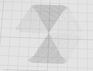
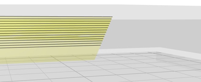
Roughing stoped at flat above part bottom. Here’s a part that I made with a brim to induce an earlier Dx version to rough like I wanted:
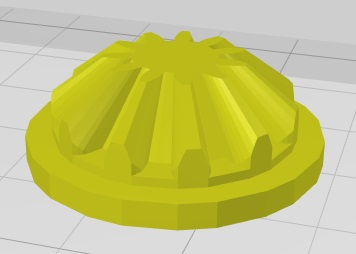
D7 roughing produced this path:
It generated the outer perimeter like it was going to cut the outline all the way down, then stopped at the flat without continuing down around the brim for which the outer perimeter was generated. If intentionally stopping here, the path around the maximal outline of the part is not needed - and I’d rather it go all the way down (mod tabs or thin remaineder). (also an example of where I’d like the “wide” outline option) -
I’ll vote for prioritizing solid layer-by-layer roughing over depth-first roughing. Depth-first reduction of lifting moves adds non-essential benefits of speed over multiple (sub)pockets and reduction of localized wear on Z mechanism.
Outlining:
-
Outlining with “wide cutout” does not double interior void perimeters
bottom slice - figure is not in a pocket -
Outlining with “wide cutout” does double convex interior outlines that are not void cutouts
Shows slice above pocket floor.
Speculative question: is there any use case for wide/double outlines around sloped surfaces? For a slope just above a vertical surface there may be two outlines (only) around the first few setback layers, but they are 1) the single outline and 2) the path above the maximal perimeter outline below rather than two offsets from the part surface. There might be some simplification to gain from asserting that any perimeter segment that is not directly above the maximal part perimeter below it will not have any further “wide” offsetting but only its single outline. anything else between the single outline and the max part perimeter will be normally generated area fill.
-
Win: depth-first outlining is doing well with order of cutting outlines - I think the incremental gain for depth-first outlining is greater than the incremental gain for depth-first roughing
Rendering
I get that refactoring rendering is forward-looking work.
2.3.Dx rendering has been flakey for me. The following seems pretty consistent:
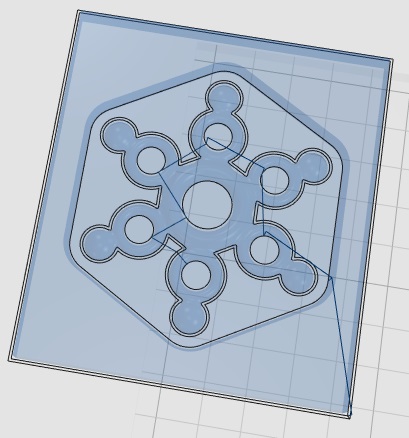
After slicing (not preview), the ghost part and slices vanish, leaving only the ghost stock box. Sometimes the top slice is vaguely rendered where it coincides with the top of the stock.
Solid or wire renderings of the part will be visible.
On selecting preview, the ghost part remains invisible but the toolpath is rendered normally.
After slicing the ghost part will be visible from below the work surface, but it occludes the toolpath as if a solid rendering.
On selecting the preview display, the ghost part and toolpath will render normally.
Viewed from above the work surface and below the level of the stock top, the ghost part may or may not be visible. When rendered it is seen through the side of the stock, but rendering depends on the viewpoint being below the stock top level rather that viewing thru the side of the stock: when the part is rendered at all at this level, rolling between just above and just below the level of the stock toggles rendering off or on.
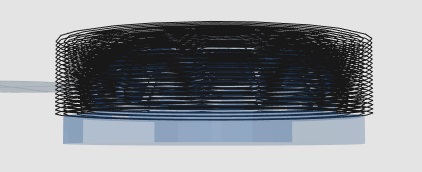
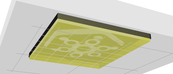
When the sliced part is not visible from between the work surface and stock top, it becomes visible when the front clipping plane moves inside the stock. The following two pics show the sliced and preview renderings from the same viewpoint with the front clipping plane intersecting the stock side. In the sliced view a) the toolpath is rendered or not along with the ghost part, and b) where rendered, the ghost part occludes the toolpath.
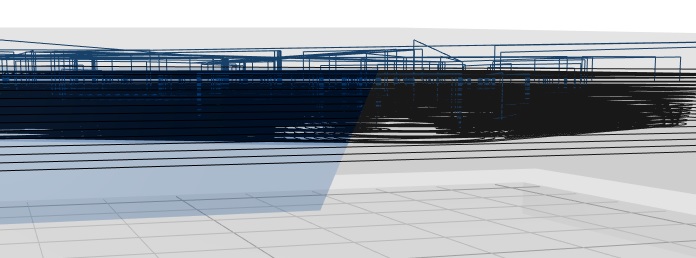
Also advancing the clipping plane into a void in sliced ghost part will reveal the paths inside the void - as with a solid rendering.
Adding a second part to the work surface adds another wrinkle to rendering. After slicing one of the ghost parts and toolpath are rendered – if the view point is off vertical (i.e. “home” not “top”). While orbiting an off-vertical viewpoint around the platform, two parts alternate which one is rendered. It looks like it’s always the more distant part (more obliquely viewed). At transitions - same distance from both parts - it may be possible to find views where both or neither part are rendered. As with a single part: at some angles the top slice is vaguely rendered.
In this case, unlike the single-part case, when a ghost part - and path in slice view - are not rendered they are not rendered when view from below either so they vanish entirely.
A solid or wire model will be rendered, but in sliced view the non-rendered toolpath will remain invisible. Except that when viewed from directly below, both parts are rendered.
In preview, the ghost parts alternate rendering but both toolpaths remain rendered normally.
KM errors
-
Often when adding a new part after clearing/removing a previously imported part, KM reports an error loading the part and calls for refresh. I’ve seen this at least once when adding a second part (without removing first), maybe after some time but as long as the Onshape inactivity timeout
-
I saw this once and don’t know how to reproduce it:

Colliding G0 found?
Something I mentioned in email a while back:
I’ve had gcode output with variously more or fewer colliding moves like this:
G1 Z-1.9661 F2500
…
G1 X99.0817 Y37.0804
G0 X162.9091 Y99.0712 Z-1.8046 F2500
G1 Z-1.9661
The G0 includes a clearance height appropriate for the lateral move, but it moves diagonally to that height above the target point, raking the part on the way, then feeds back down to complete the move.
I think I found the cause, then left it alone since you’re refactoring all around there. It looks like the relevant code has survived in mode/cam/prepare.js
The first problem is self-inflicted: when “tolerance” is set to something larger than the required Z lift, mustGoUp does not get set. Fair enough[*]. Then it should move like there’s nothing in the way. Doing the ramp up to a level that it’s already decided to not clear then feeding back down slows down for no benefit.
After mustGoUp is not set, it is tested to see if the spindle should be lifted before the lateral move: no.
Then mustGoUp or the likely condition point.z < maxz are tested to see if the lateral move should go to the higher level: yes. And so it does.
Suggestion: after lifting or not lifting before the lateral move, it should just make the move at constant Z without testing again. If point.z < maxz is a relevant condition, it shouldn’t be omitted from the pre-move lift test – ??in which case skip the comparison with tolerance??
UI whingeing
-
Wishlist: An option for Onshape-like mouse button mapping – at least when running in Onshape – would simplify switching between part studio and KM tabs.
Onshape complicates that with multiple mapping options. Copying the default would help more often than not. Maybe Os exposes which mapping is selected? -
Minor quibble: separate checkboxes for different milling operations seemed useful for distinguishing what’s what. Limiting checkboxes to displayed operations would help to declutter.
-
[*]from the above Colliding G0 question: Small values for tolerance slow things down. Large values don’t appear to affect slicing for roughing or outlining, so why not? The “profile” operations show clearly the effect of large “tolerance” values. However, the naive user
 may not get to see that effect in the surfacing operation if s/he doesn’t get past crashes in roughing. A simple mention to look at XY profiling for effects of tolerance values might help.
…
eh, more, but I’ve got to send this for now.