First off - what a great application Kiri:Moto is, thank you to the builders & contributors!
I recently got a CNC router, and the kind folks at Makerforums.info recommended Kiri:Moto
Goal
My goal is to create 2D (and soon, 3D) graphics - and then carve them into wood - signs, etc.
I was able to create text in Inkscape, and then import the paths as SVG into KM, where I was able to make a 3D carving plan for the CNC router.
Problem
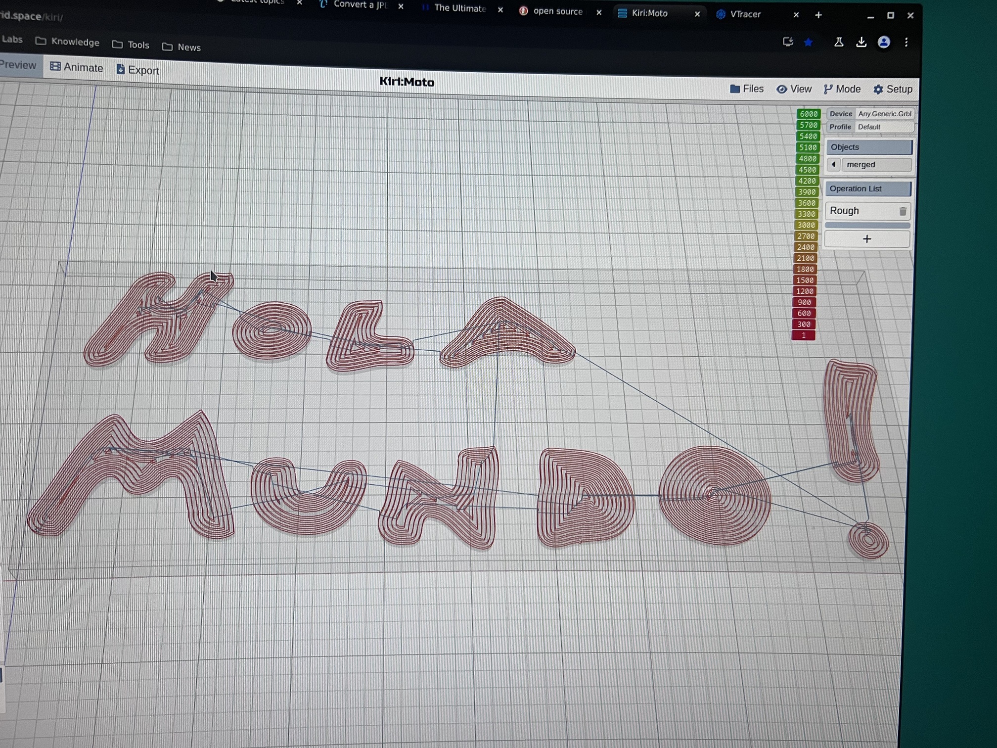
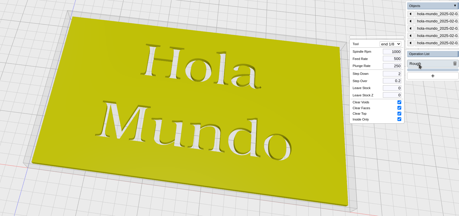
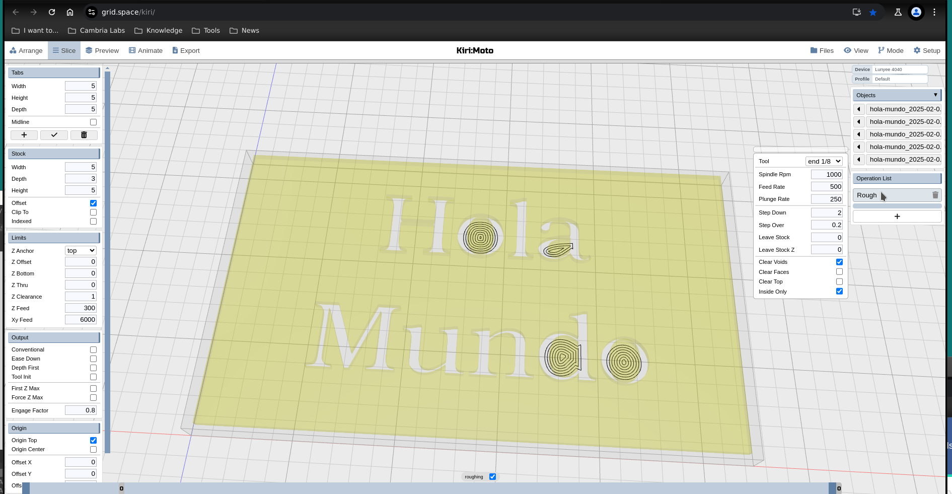
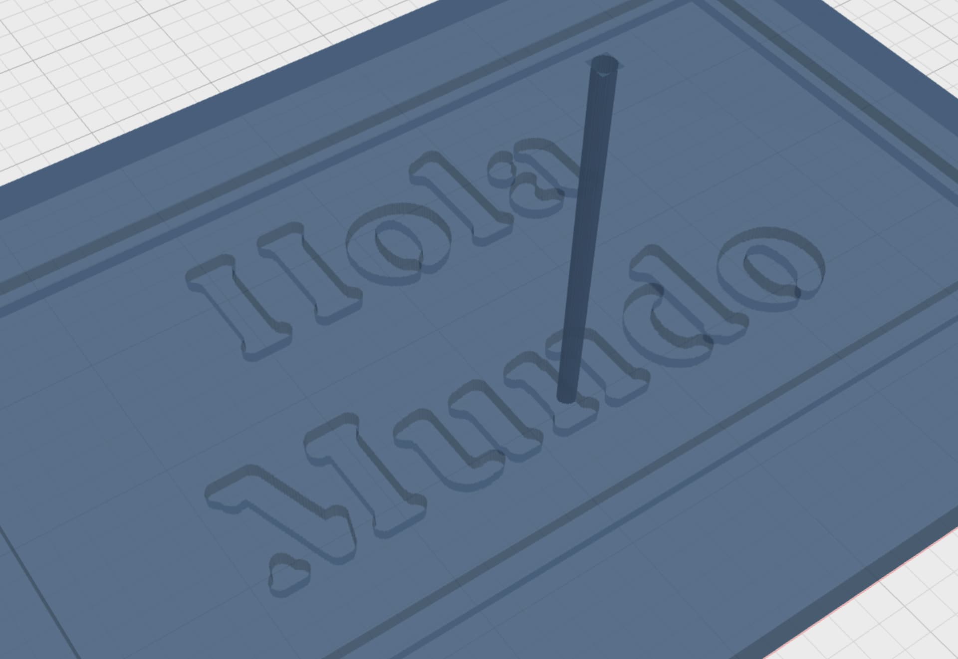
An issue I’m experiencing, and I could use help with - in KM, the holes in text are getting carved/drilled, where I’m expecting those empty areas to be left alone by the tool plan. Instead, it seems like KM literally double-downs on this area, carving the holes extra deep!
You can read about the context and see the SVG I’m using in this thead:
When I get back on the computer, I can provide KM project files or other details as necessary. Hoping this is enough to start defining the problem, and perhaps find out if I’m missing a setting or option.
Questions
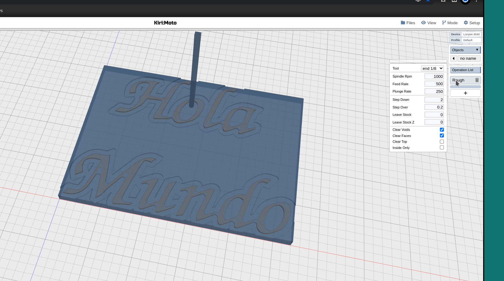
Is “Rough” the right operation I should be using for this type of project? I couldn’t get “Pocket” to work.
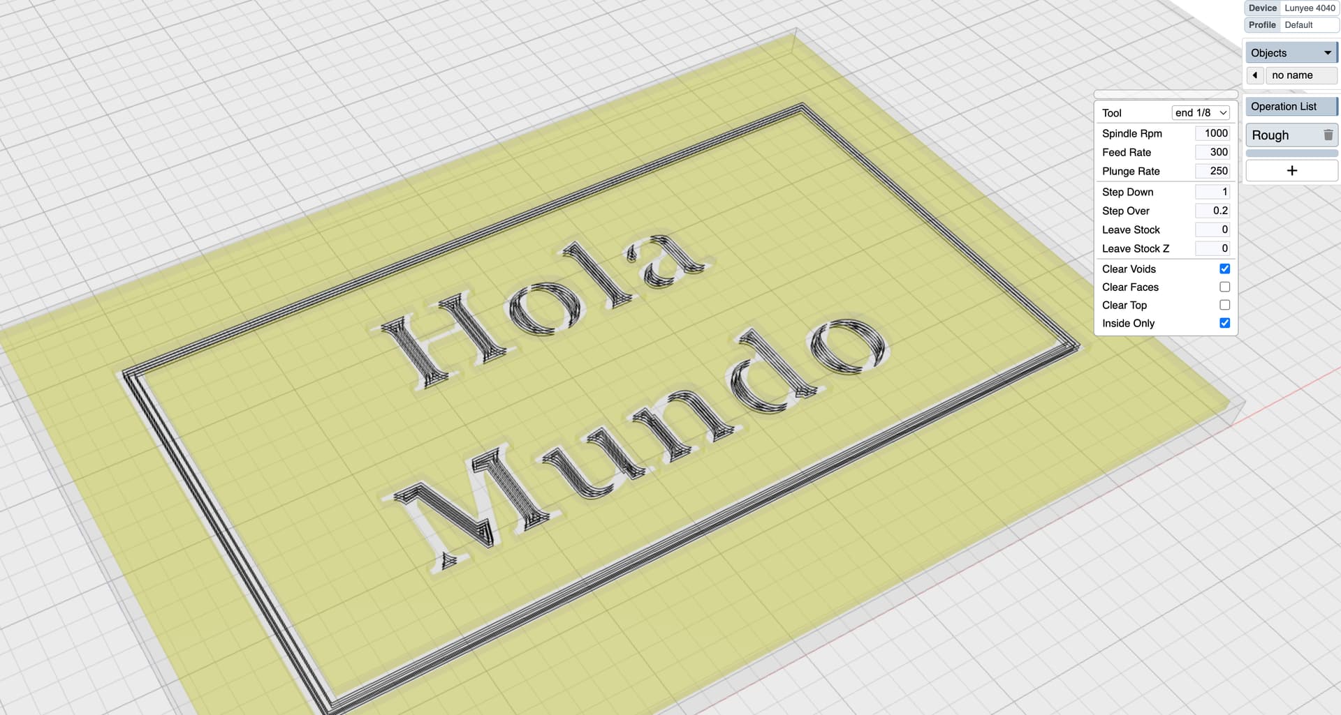
In your workspace, the roughing op is working as intended by clearing the space above the letters. If you want to avoid this, then use z-anchor “top” instead and change the op by unchecking “inside only”. That way there is no material to clear above the letters and it will also cut the outside. Here is a version of the workspace with those changes.
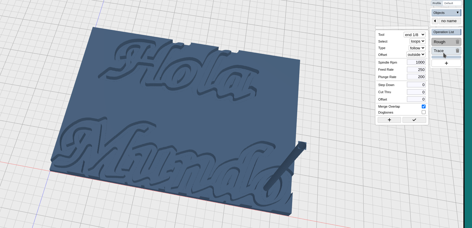
I’m also attaching a workspace that uses the trace operation instead of roughing to cut out your letters. It relies on a fix only in version 4.1 of Kiri:Moto, so you will need to use the center drop down menu (under the app name) to select a new version. Then shift + reload the page and import this workspace.
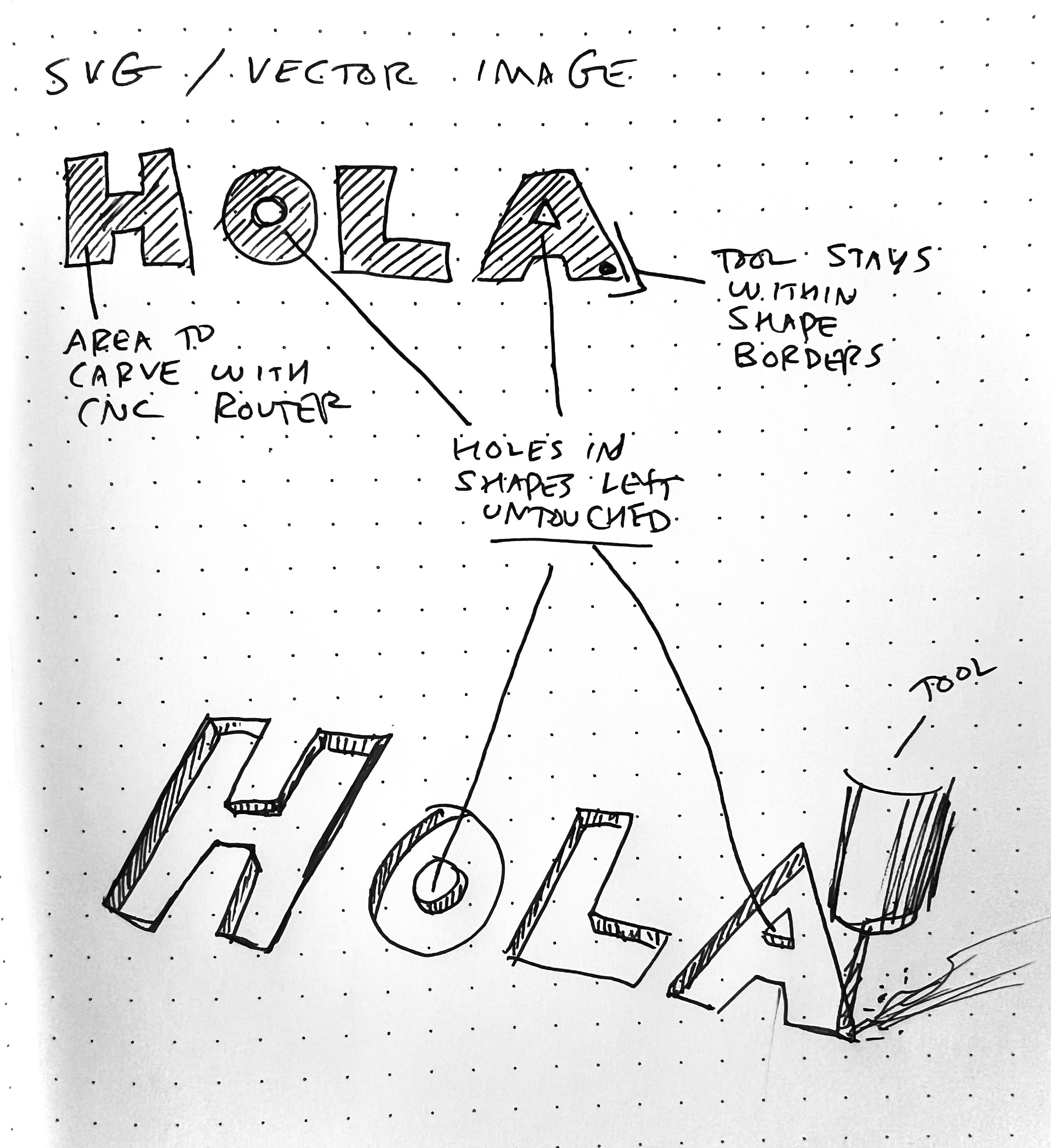
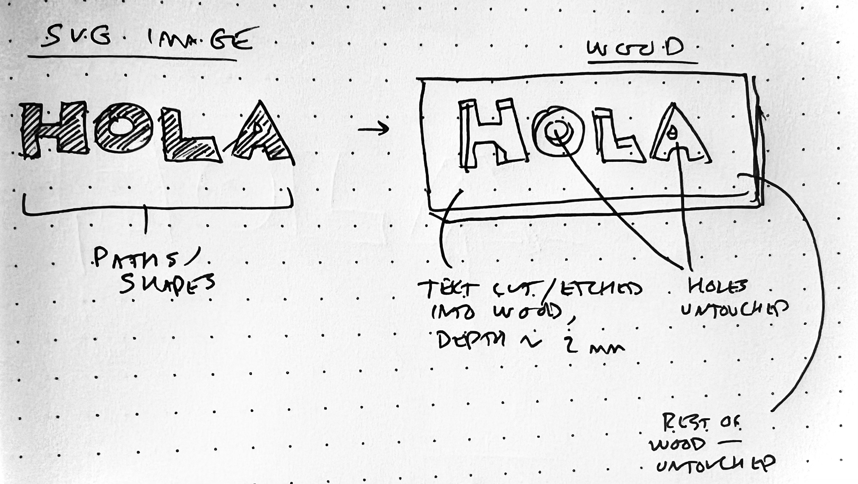
I notice that the plan has the tool effectively trace the edges of my shape, cutting on the outside and leaving the shape. What I am hoping to achieve is ONLY cut within my provided shape (not around it), and when there are holes in a shape, that those areas are left untouched by the tool.
Below is a screenshot of the Trace file you provided. For some reason, I could not get the tool plan AND the “Show model” of my shape to appear on the same screen.
I notice that this tool plan traces the shapes edges, expanding the shape’s size. As I mentioned in the previous comment, I am hoping to import an SVG shape, and effectively clear JUST the inside of the shape, and when there are gaps/holes, to have those un-touched by the tool.
I see! The easiest way to do this is to put an enclosing box around the letters in the SVG, and then they will come in as a negative space. Then it’s easy to use a pocket or (rough + inside only) or trace to clear them out.
Thanks for your suggestions @stewart - I tried them out, and here are the results. Still not able to achieve the SVG text / carve operation…
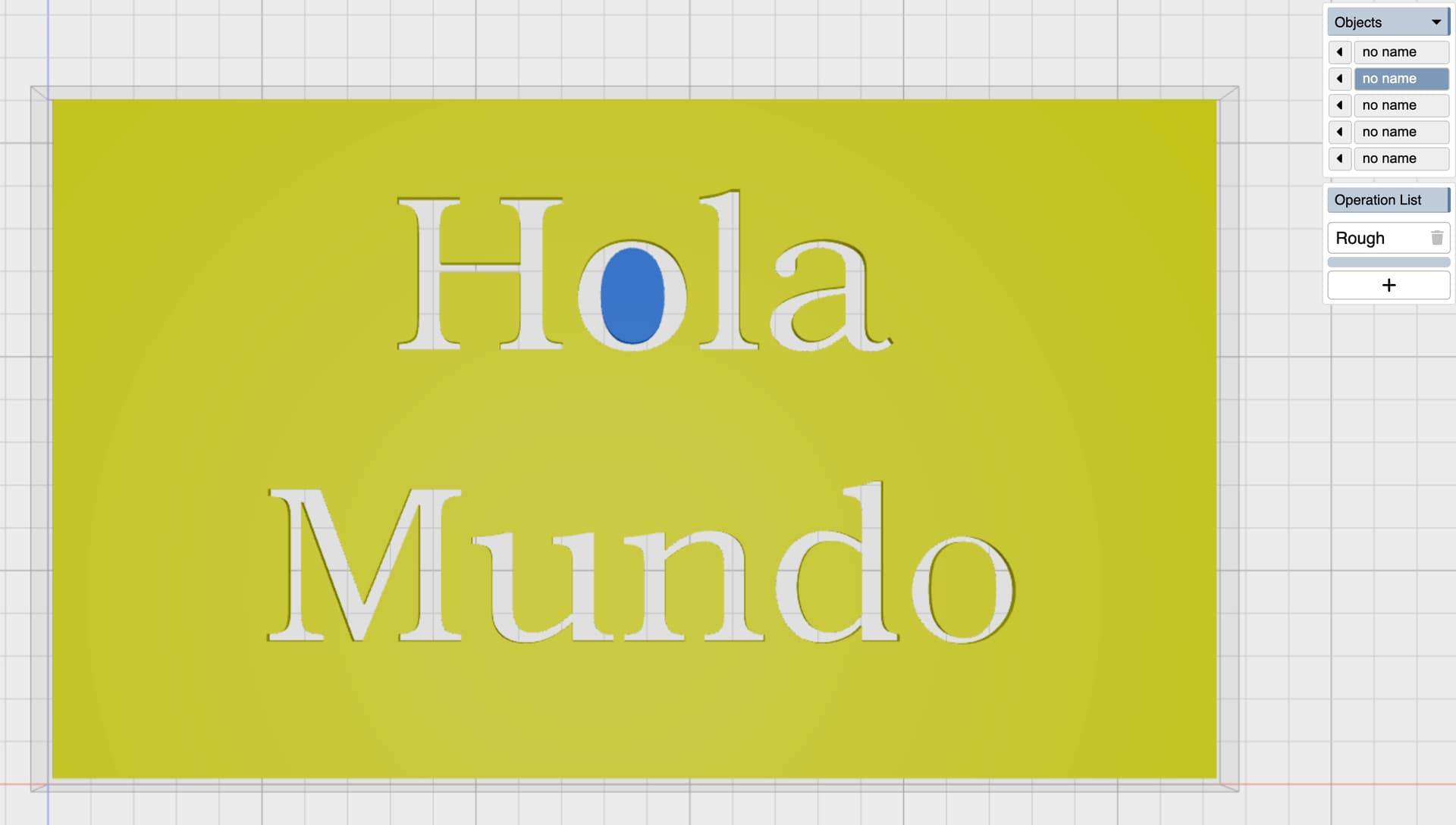
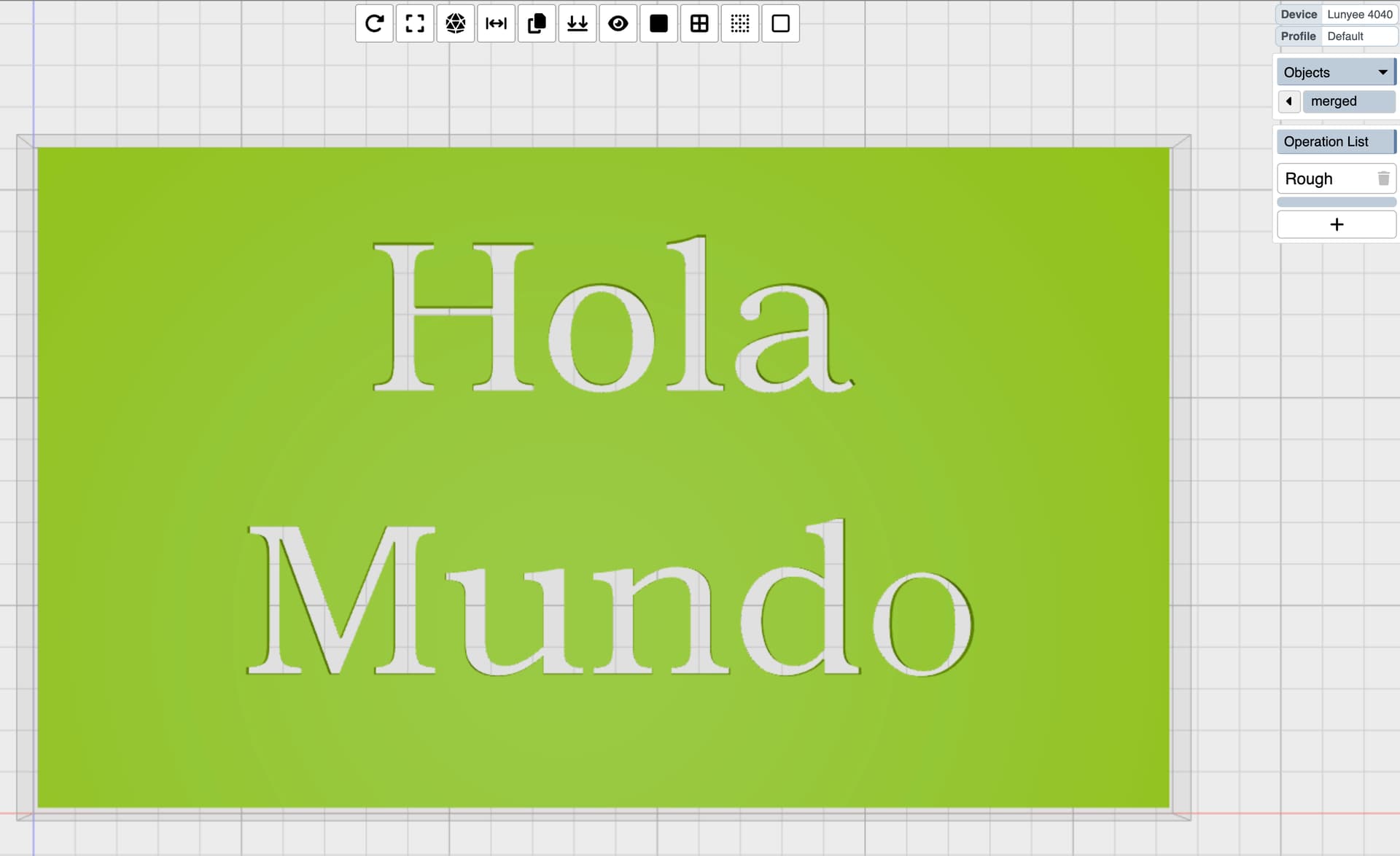
In Inkscape, I created text (“Hola Mundo”), and a box, and then did a Path->Difference operation to create a box with “Hola Mundo” cut into it. Added color, and saved the file as SVG.
Here is a link to the SVG file (Note: I wasn’t able to upload the SVG to the forum)
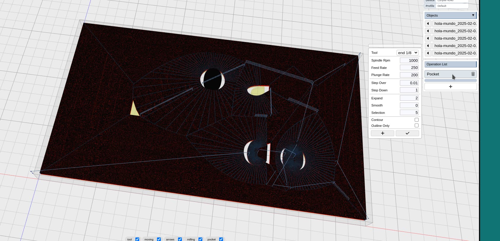
I imported the SVG file into Kiri;Moto, and tried Pocket operation, and then tried Rough + Inside Only operation, but was not able to get the result I am looking for.
@stewart, one thing I wanted to ask further. On my earlier file, the Rough operation worked perfectly… except that it also drilled out the holes in the letters. Is that intended functionality? On the Makerforums thread, someone imported my file into LaserWeb (I haven’t tried that tool yet) and it appeared to work as intended - carving the text, and leaving the gaps un-touched. How can I get that result with Kiri:Moto?
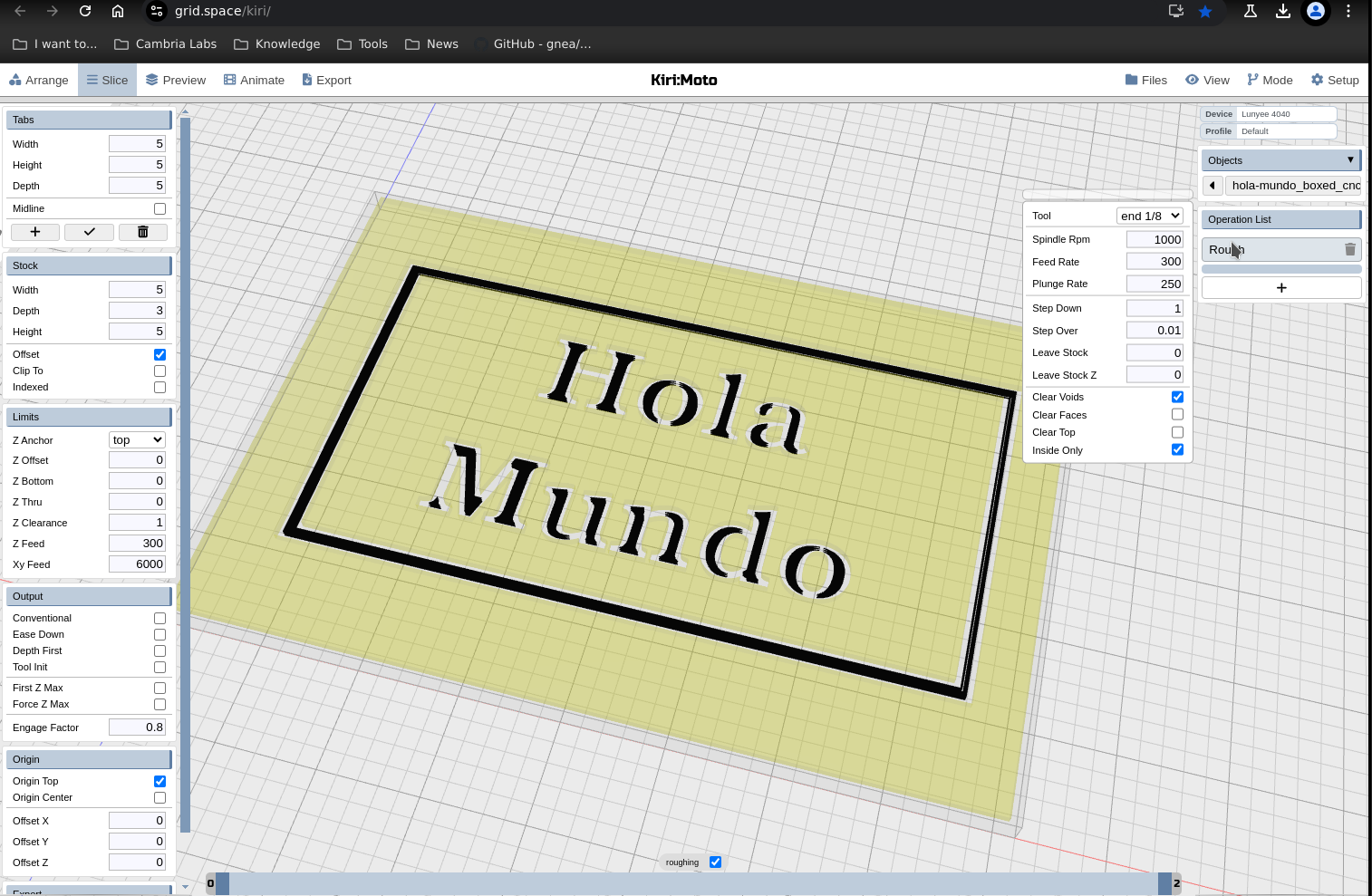
drop you workspace here. it still looks like you have “clear top” “clear faces” set for you roughing op and the workspace is maybe not using “limits → z-anchor → top”
if it’s not clearing out the letters with that setup, it’s likely because the endmill does not fit inside those channels.
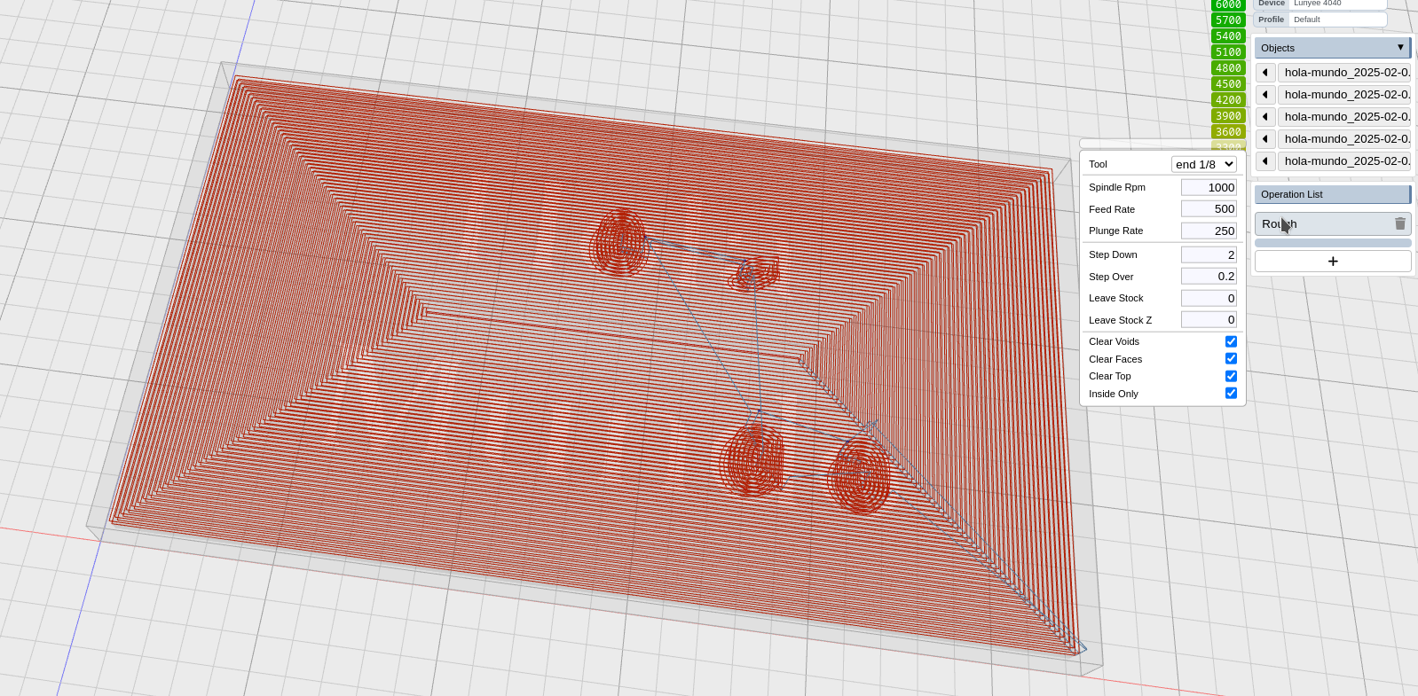
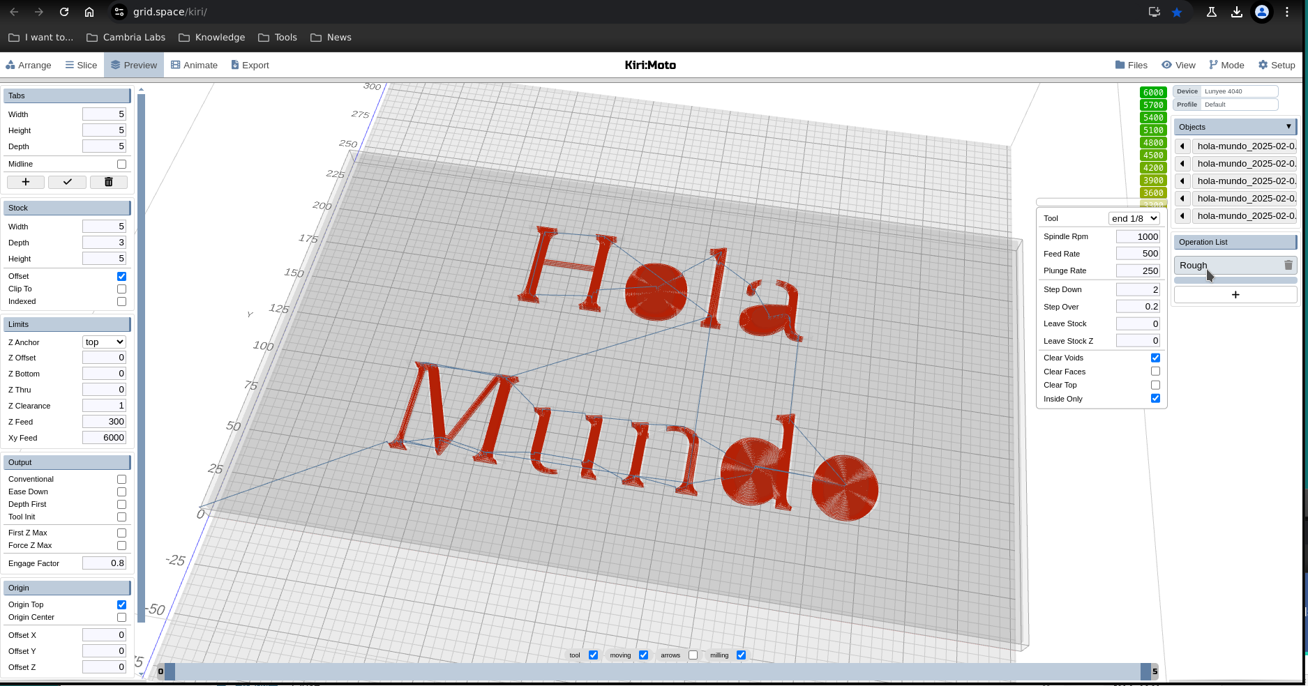
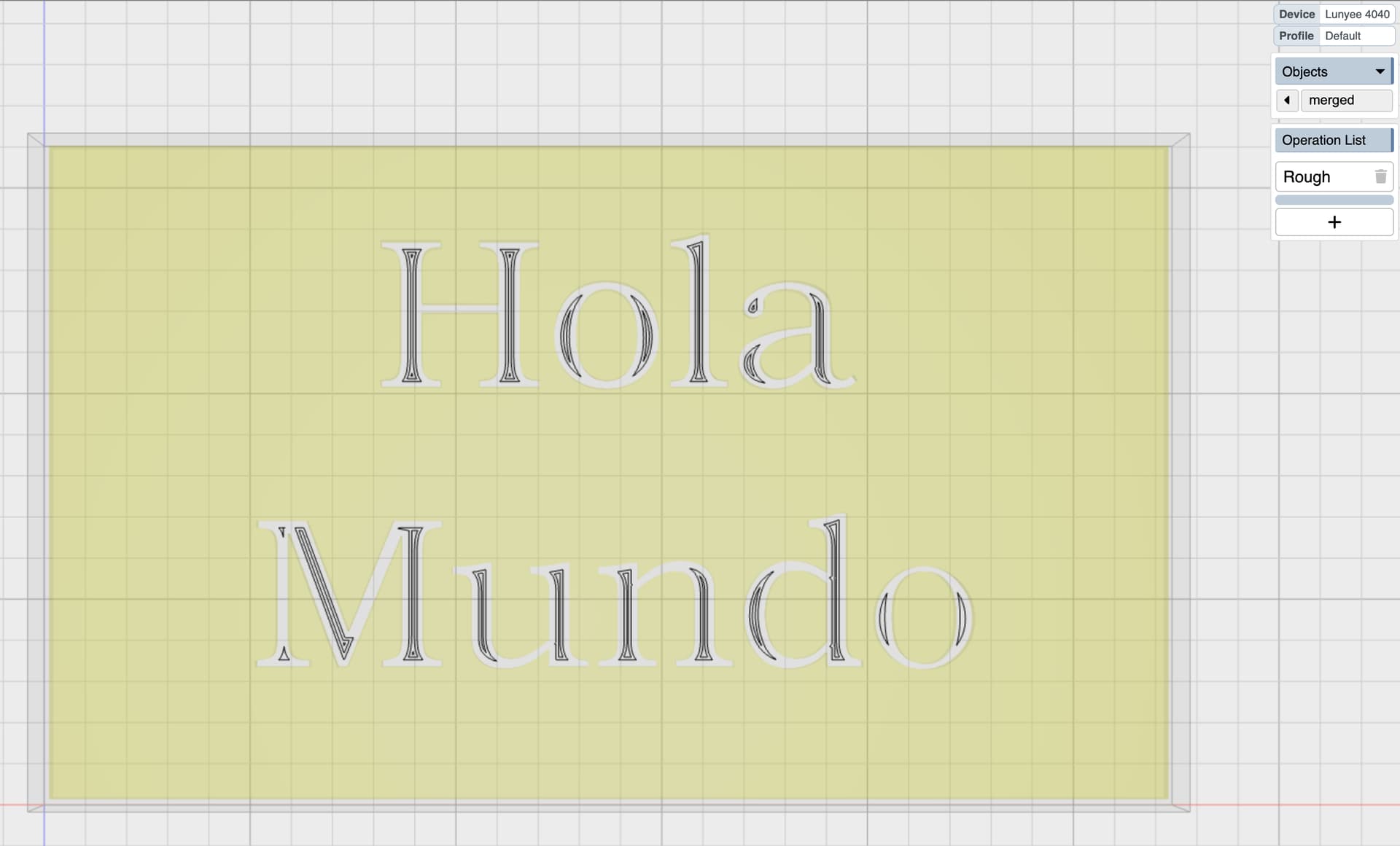
You mentioned that the endmill may not fit inside the channel, as a test, I scaled up my model by about 5x. I see now that there are toolpaths inside of the text (good!) but there are still instructions to cut out the gaps/holes (ought to be uncarved)
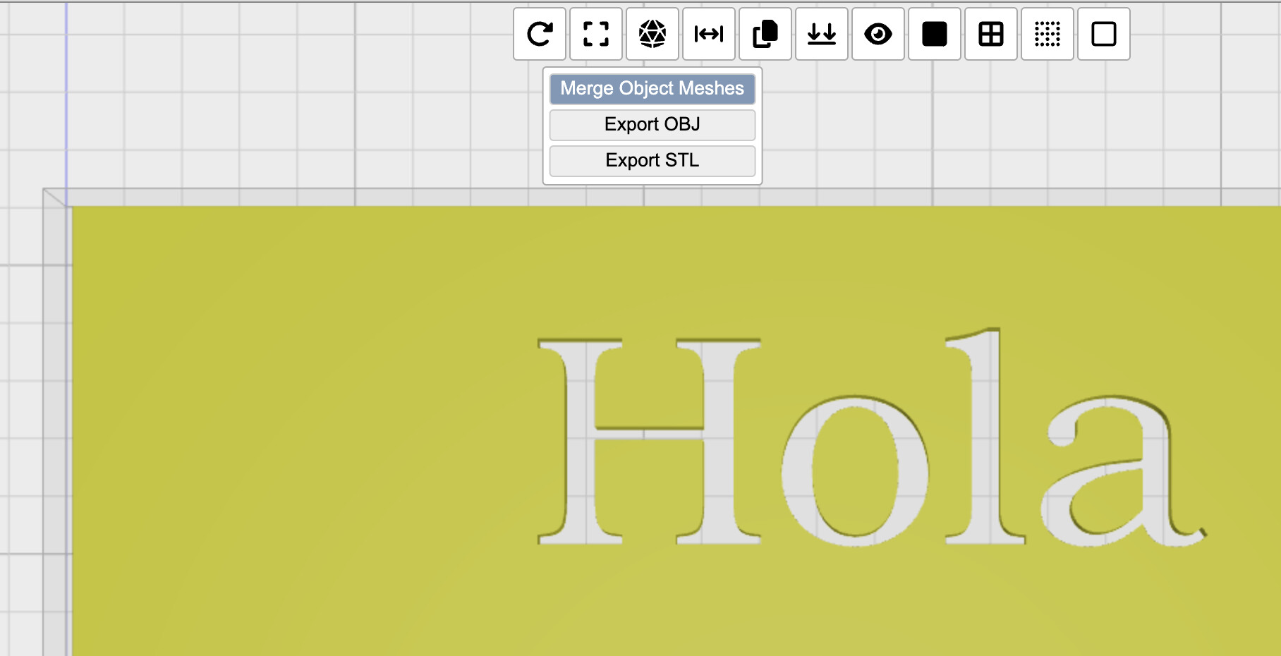
I’m kicking myself for not noticing this before, but the SVG import produce a bunch of separate objects. These need to be merged so that they’re treated properly.
I am using a 1/8" bit, and set the X scale of my object to about 200mm - feels like the tool ought to fit through the text, but have not done a detailed measurement.
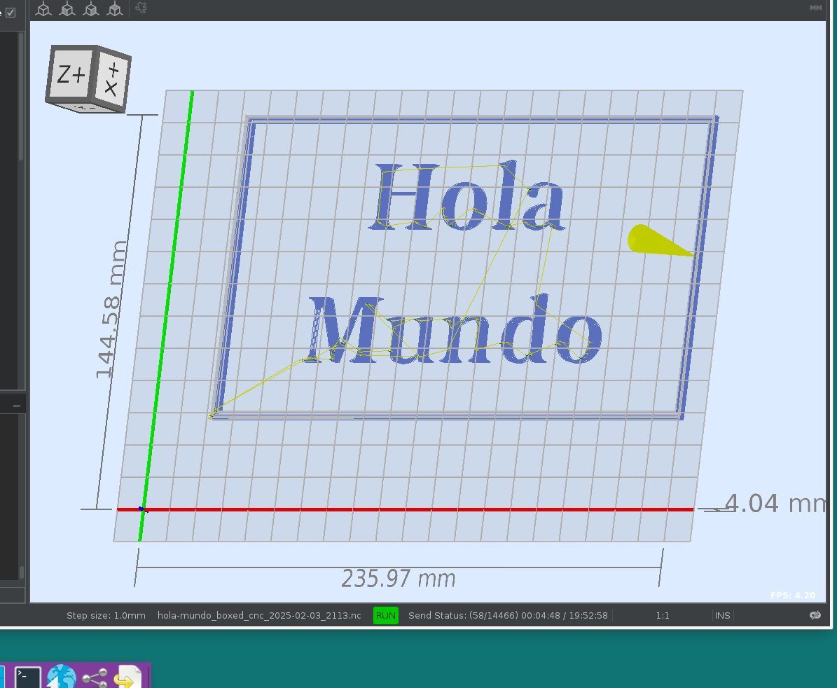
I put this file into Universal G-Code Sender (UGS) and have the program running above the board, so I can see what it will do.
Am I reading / understanding UGS’s estimated program time (bottom right of the window) as this job taking 19 hours? I am testing this on pine wood, and have the feed rate at 500. Disclaimer: CNC newbie.
What’s the best way to estimate time from a job program? And is my job plan / g-code file doing something inefficient, giving my goals (one thing I noticed is that the plan steps down several times - I was hoping - for this test, to keep the depth shallow, at 1 or 2 mm, just so I could learn…)
your step-over at 0.01% of the tool width is wrong. it should be 0.2 to 0.4 – this explains your 19 hour run time. you could also probably do this with a larger step down and perhaps a faster feed rate. you’ll have to experiment with what your machine and endmills + material can do.
also, if you run the animation in KM you will see the tool size and that it does not fit in the letter channels.