Hi All,
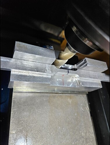
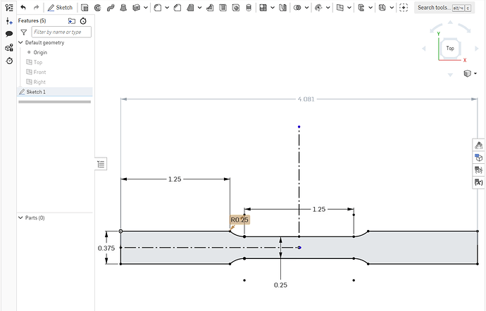
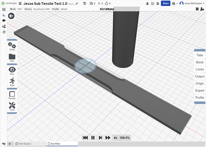
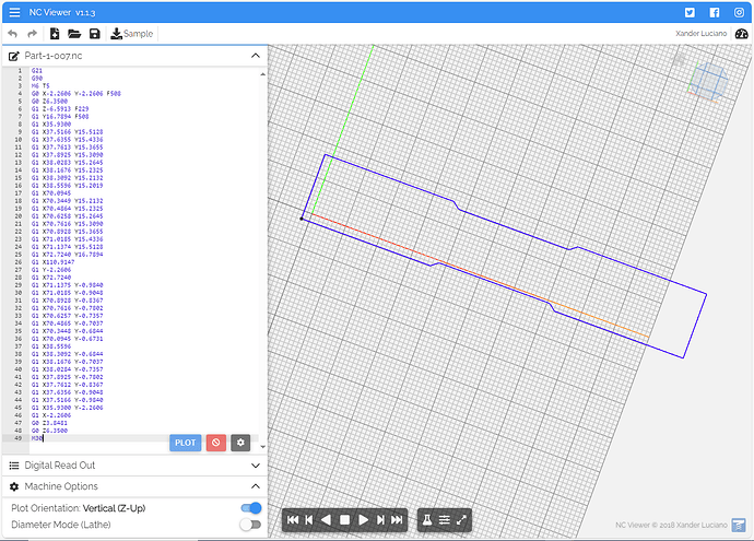
I’m trying to get a tool path for my CNC milling machine to work with my fixture. I have gCode for deferent sizes. Now I need to make new sizes. I want to use a visual tool like OnShape and Kiri:Moto. I really like how I can make a blueprint to gcode.
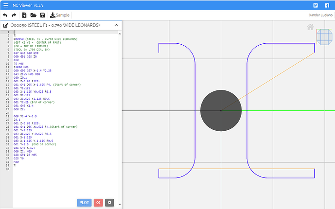
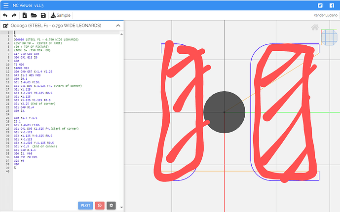
I need a tool path that looks like this.
Not the hole shape cut out
Anyone have any ideas to the get this workflow to work for this project?
Thanks in advance for your help ![]()
-=Jesse=-
P.S. Here is gCode for Refaince
O00050 (0.750 WIDE)
(G57 X0 Y0 = CENTER OF PART)
(Z0 = TOP OF FIXTURE)
(TOOL 5= .750 DIA. EM)
G17 G40 G80 G90
G00 G91 G28 Z0
G90
T5 M06
S1000 M03
G00 G90 G57 X-1.4 Y2.25
G43 Z1.5 H05 M08
G00 Z0.1
G01 Z-0.03 F120.
G01 G41 D05 X-1.625 F4.
G01 Y1.125
G03 X-1.125 Y0.625 R0.5
G01 X1.125
G03 X1.625 Y1.125 R0.5
G01 Y2.25
G01 G40 X1.4
G00 Z2.
G00 X1.4 Y-1.5
Z0.1
G01 Z-0.03 F120.
G01 G41 D05 X1.625 F4.
G01 Y-1.125
G03 X1.125 Y-0.625 R0.5
G01 X-1.125
G03 X-1.625 Y-1.125 R0.5
G01 Y-1.5
G01 G40 X-1.4
G00 Z2. M09
G28 G91 Z0 M05
G28 Y0
M30
