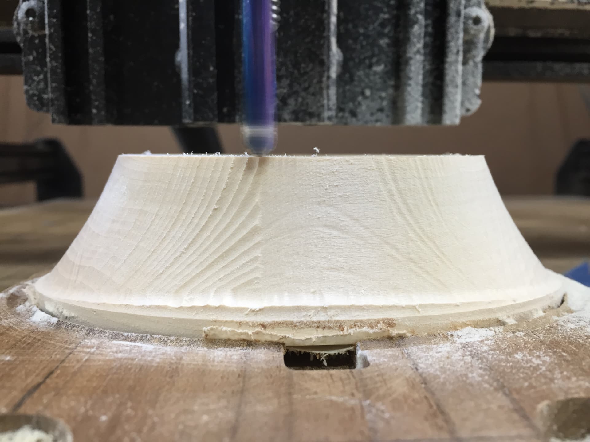
Look at the photo. There is a crown where it ought to be flat from left to right. Why is this happening?
workspace (1).kmz (921.7 KB)
Look at the photo. There is a crown where it ought to be flat from left to right. Why is this happening?
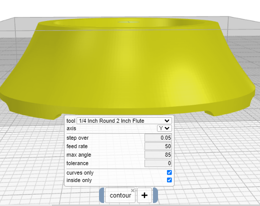
What does “inside only” actually mean? Does it mean, keep the tool tip within the part boundary? Is that always the case for all route commands “inside only” selections?
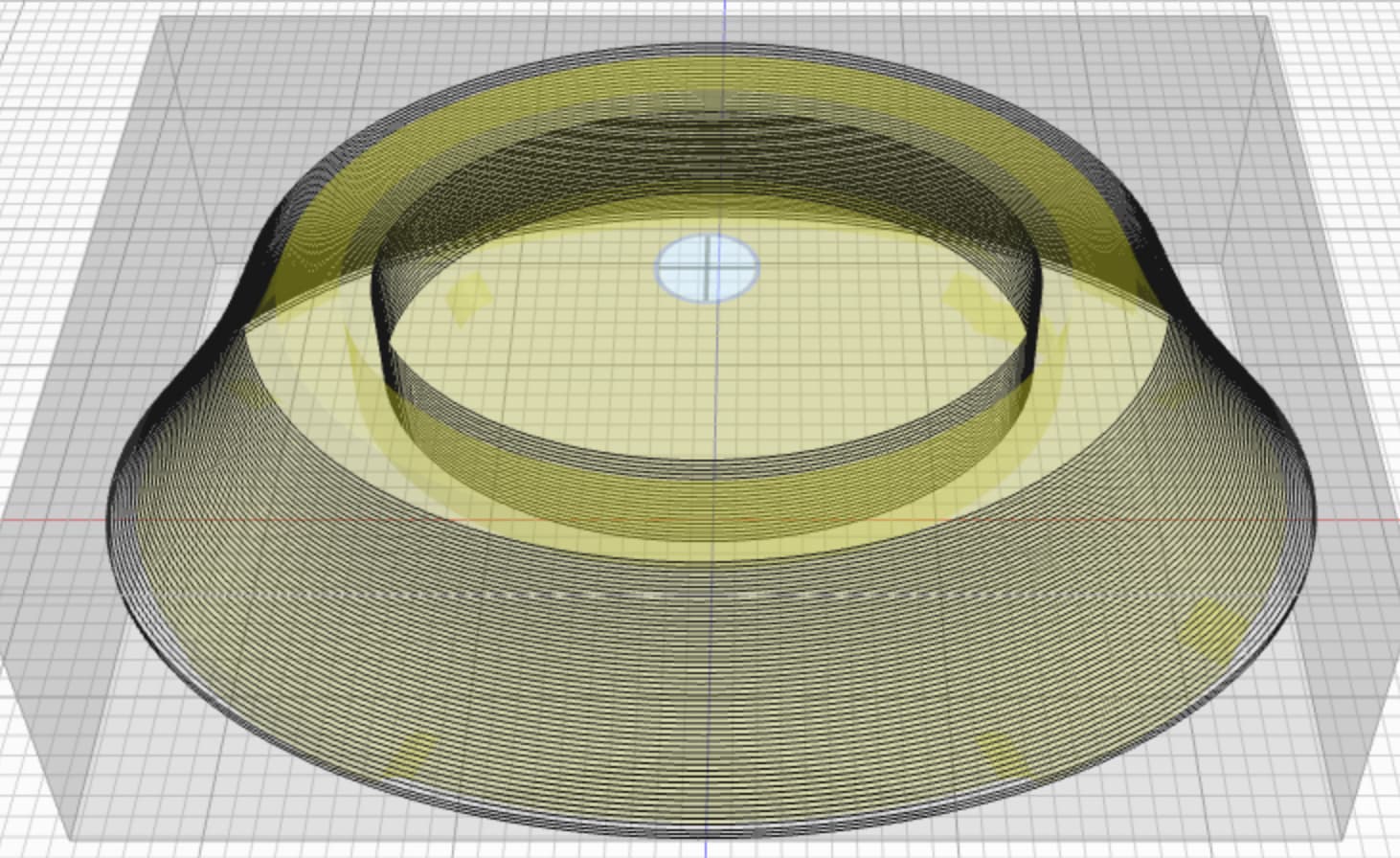
The result includes the top inside pocket? How can this be avoided?
Another observation. The part was not routed correctly using the “inside only”. It did not result in a sharp bottom edge. It has a fillet. So does the "inside only mean keep the bit perimeter inside the part boundary? It seems to have routed out too much exterior wall material.
Post process shows the result clearly. Preview gives an idea what is happen. However, it is hard to catch nuances like what happened here. Once I flipped the preview over it became evident. Are you aware of any tool that renders GCode to the final routed result?
Inside only for contours keeps the tool tip within the “shadow” of the part. If you disabled “curves only” then vertical and horizontal faces would be cut as well. You can “animate” after preview and it will run the gcode through a simulator and show you roughly what you will get. It’s computationally expensive, so you can watch while it does it 
I preview always. Animate helps some. Very easy to miss subtleties.
So you are not aware of a GCode rendering software?
Why did curve “inside only” remove too much material?
Do you mean rendering of paths or simulating cuts? I haven’t looked for either in a long time since Kiri:Moto has it’s own built-in viewer.
If the mill didn’t follow the preview path for “inside only”, I do not have a ready answer. I am not aware of any situation where the gcode generated does not match the preview.
Rendering of the finished result. The software would need tool information and raw material information.
I am not aware of one. But please let me know what you find. I would like to improve animate as time permits.
A machinist mentioned to clear a face, like the one above, it is best done with a round tip bit and using a spiral cut from bottom to top rotating around the part. Something to do with the forces on the bit, it ever so slightly flexing. Plus machine tolerance. The goal being a very smooth surface. I would guess the step would be in the Z Direction. He uses Fusion 360 to accomplish this.
by round tip do you mean a ball mill? the spiral path (a 3D path in x + y + z) is not yet implemented in Kiri:Moto
I believe he did say Ball mill.
the spiral is a nice touch. but how smooth it is mostly depends on the “step” or spacing of the cut lines. you can achieve most of that in KM with an outline operation + ball mill and a small step down value (z)
On a curved surface like above?
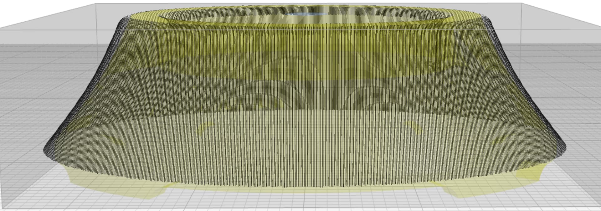
One a part like this is it recommended to do both a X and Y Curve Path? The Y Path is smoothing the front and back surfaces well and the side surfaces not as well. Step Over is 25 mils.