Hello, I hope someone can help an old model engineer learn new tricks!
I am new to CNC milling, and I have unexpected results that I strongly suspect are due to my using the wrong Post Processor. I am using Onshape for CAD, Kiri Moto for CAM and the machine controller is UCCNC. I have, without success, looked for information about how to create a PP or finding much of a description outside what it does. Any advice about where to start would be greatly appreciated.
Many thanks.
Brian
Hi Brian,
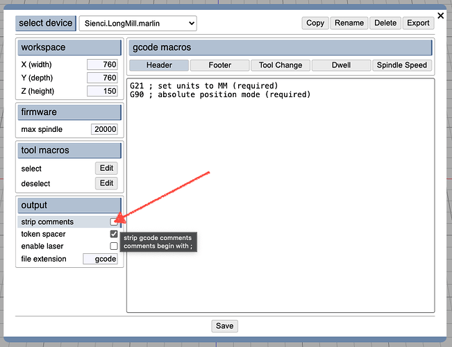
What flavor of gcode does your sender / controller run? Will it accept GRBL like code? What are your unexpected results? Have you tried customizing one of the stock devices and editing the gcode macros?
Stewart
Hi Stewart, thanks for responding to my plea for help. UCCNC say in their manual “When developing we followed the industry standard RS274 format and used the same codes which codes this standard implements.” Does that tell you anything?
The problem I am having is the controller does not seem to give the Z axis time to fully retract before moving the table. When I altered the setting to increase clearence from 2 to 10mm it makes no difference. I do not have the knowlage to alter the PP so any pointers wbere to look would be much appreciated.
Many thanks
Brian
What have you tried to mill so far? Are you doing test “air cuts” to test kinematics? Have you tried writing small gcode programs to test simple box movements? It would be surprising if it mixed moves between gcode lines. Is it possible your Z axis scale is wrong? I feel like I need a lot more info. What kind of machine is this?
I have done a number of tests cutting air, which seemed promising. I have also cut a shape out of a piece of wood. This is when I found the top face of a pocket being cut through because the Z axis had not cleared the top face. The first time it was set to +2mm, the second +10mm with the same result.
The UCCNC manual says unrecognised code is shown in red while recognised code is in white. On my setup, the code at the start has quite a long list in Red, while the G code is white.
I have entered the G code in the MDI and seen the machine movments were as intended. The three axes have been calibrated and what has been machined has come out the correct size.
do all the red lines start with “;” which are comments? are there any red lines after the header?
Yes, all the Red lines start with “;”. The only red line after the header comes at the end where there is another semicolon and some text saying “ending rough op”.
Hi Stewart,
Well, I did as you suggested and disabled comments and then ran the g code on the mill. Things were looking good up to halfway through, when the Z axis failed to rise and the cutter crashed through the job. Luckily, I am machining wood, so no damage was done. Up to that point, the Z axis cleared the top of the job by 10mm as I had set it. I have pasted two pieces of the code, the first one shows where the machining was going well, and the second is where the tool crashed through the job.
G1 X-2.1885 Y-0.0106
G1 X-1.9443 Y-0.6466
G0 Z9.9900 F480
G0 X12.5000 Y9.5000 F2100
G1 Z-1.4900 F200
G1 X152.5000 F210
G1 X12.7601 Y14.2420
G1 X12.7586 Y9.7579
G0 Z9.9900 F480
G0 X3.8690 Y-4.5000 F2100
G1 Z-13.2164 F200
G1 X161.1310 F210
As far as I can see, the second piece of code should have worked like the first one. I am wondering if I have a problem with the hardware. They are all new components, but I realise that does not rule out a faulty unit or connection.
Many thanks Brian
if you don’t see a crash in the preview (P) or in the animation (G), then it is most likely some sort of hardware failure. it could be a loose cable. but if it’s always a Z failure to raise, then it’s also possible the Z axis is under-powered or slipping/skipping under load.
Hi Stewart,
I have found a problem with the Z axis drive on my machine. The arrangement uses bevel gears, which are quite badly worn. This obviously must be addressed, which I will now do.
Thank you for your help.
Brian
This makes sense. Thanks for the update!
