I am relatively new to Kiri:Moto so I hope I am missing an obvious approach to what I’m trying to do. I have pre-cut pieces of 3/4" plywood that is 4 9/16" wide and of varying lengths. I would like to cut out only the finger joint ends with dogbones in the corners (left picture). But, when I choose the outline operation, Kiri:Moto obediently generates paths around the entire outline of the modeled part. Is there a way to edit the outline to restrict it to one area?
I am resorting to the creating a model with a .125" offset edge and using the tracing operation with a .25" endmill to just do the interior finger edges (right picture). Any feedback is appreciated!
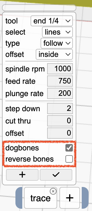
Hi @rogerbaas and welcome. I’ve just added dogbones support to traces. Because open polylines don’t have a “direction” (clockwise/counter-clockwise), there is also a “reverse” checkbox in case the algorithm guesses incorrectly. This is accessible via the version menu top-right … select KM version 3.9, which is the development branch. I look forward to your feedback.
Thank you, @stewart! I switched to 3.9.D7 and tried the trace operation with dog bones and then reverse dog bones enabled. Unfortunately, it did not add the dog bones in either case. See below.
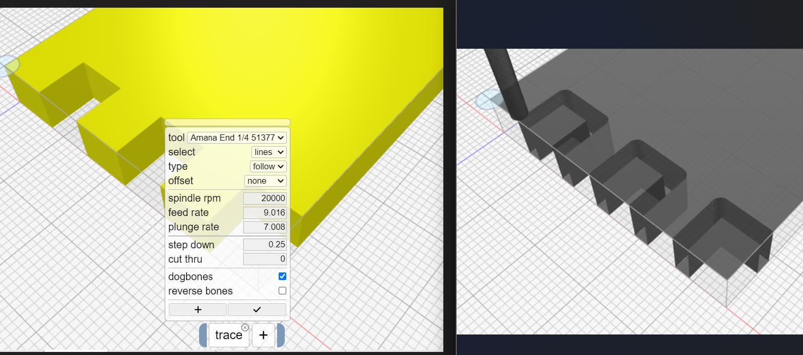
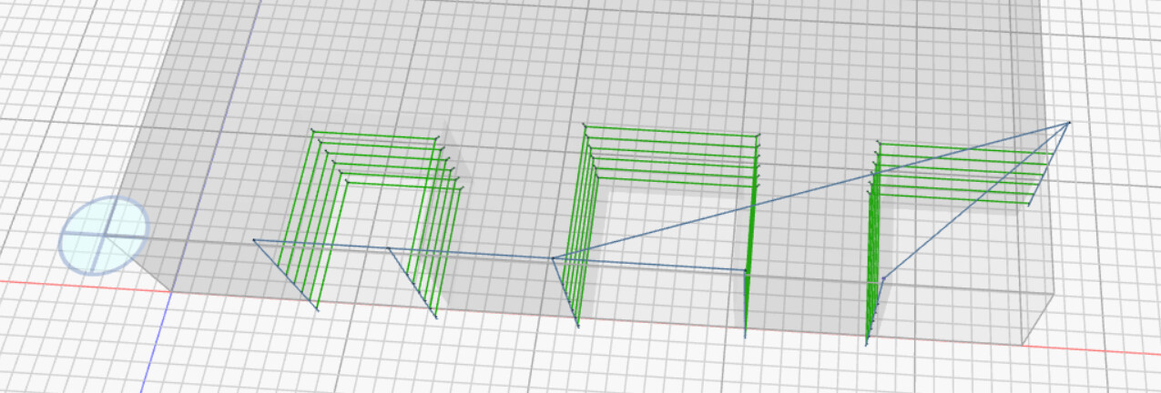
@stewart, the dogbone on traces function works now! As you might guess, however, the next issue is the direction of traces, which does not seem to be definable. Even though I selected the interior edges of each finger in a clockwise order, one finger cut inside and two cut outside the trace (see below. select=lines, type=follow, offset=outside). Reversing the dogbone caused one outside and two inside . Unless there is a deterministic way to define the trace direction (which might exist and I am not aware of it yet), the dogbone on traces functionality may not be very useful.
In the meantime, I ended up modifying the CAD model by adding .5" of “fake” material on the bottom and right edges to form three enclosed square openings rather than open fingers. Using outline mode, Kiri:Moto happily cut these three square holes with dogbones. Then, on the CNC, after probing to find the origin, I moved the cutting head -.5" in the Y direction and re-zeroed the Y axis. That worked great.
That’s the problem with open polylines – there is no definitive direction from which to determine inside / outside. I would need to add the ability to individually reverse line orders to achieve something more reliable. In the meantime, you could split the trace op above into two: one for each offset direction. Those that were inverted could be in the second op.