I want to do something that I thought would be obvious – but I’ve been using my home-brew mill with home-brew software for so long that maybe I’m thinking about it wrong.
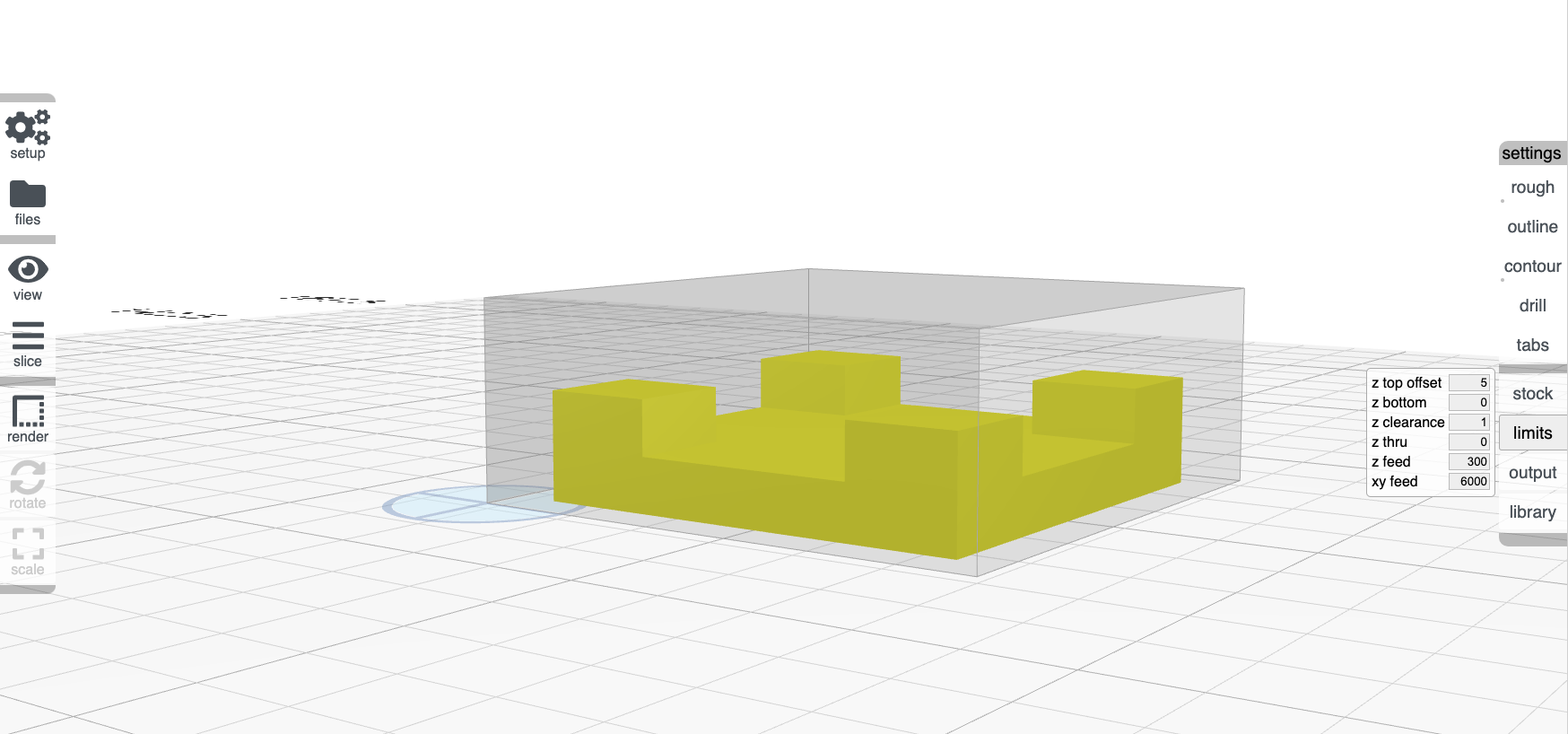
I have a part that’s roughly .16" tall. I’ll be cutting it from stock that’s .25" thick. I want the bottom of the part to be at the bottom of the stock, and I’d prefer that my G-code think of the bottom of the stock as z == 0. Before cutting I would home the cutting head at the top of the stock and tell the mill that z is now at .25". When run, the generated G-code would know to rough off an extra .09" of material above the outline of the part.
I thought I would configure this by setting stock height to .25, un-checking the “offset” box, and un-checking the output “origin top”. But while that puts my origin at the base of the stock, it leaves my part at the top of the stock, .09" above where I want it.
What am I missing? Is this not how other people use their mills?
if you uncheck origin center and top and set z top offset to match the amount larger the stock is (in the Z dimension) than the part, I believe you will get what you want.
Okay – I didn’t expect to find yet another place to adjust this behavior.
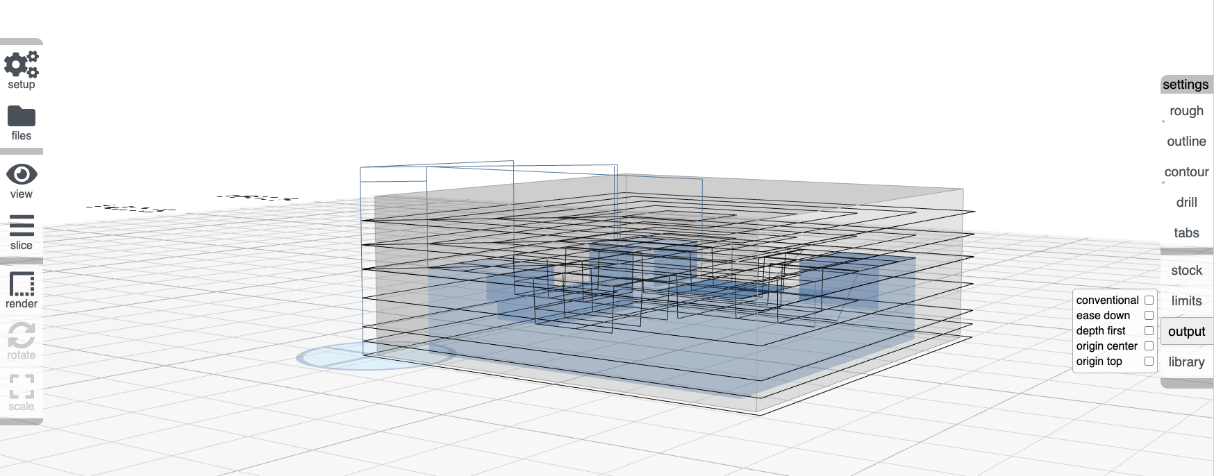
I assume that Output–>origin-center doesn’t really affect this, right? It doesn’t appear to. (I.e., that’s purely a 2D centering, right?)
I really would have expected the value you’re saying is in z top offset to be a property of the stock, not of the z axis. After all, it might change with every piece of stock.
Sadly, it doesn’t work properly. My stock is .25", my part is .16", and if I set z top offset to .09, my part ends up something like an inch below the table
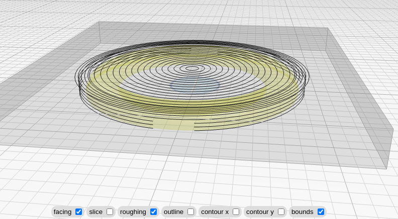
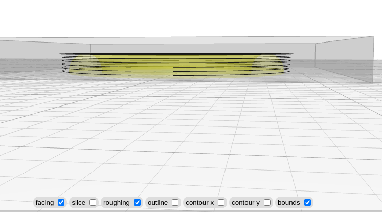
If I set z top offset to about .004, then it looks like the bottom of the part is pretty close to the table. Perhaps this is another inch/mm issue, but if so, it’s more subtle than my inner programmer can picture.
You can see from the screenshots that even though .004" makes the bottom of the part line up (roughly, by eye) with the table, the roughing cut isn’t adjusted for the added depth of the first pass. It also roughs out the whole area of the part outline, rather than just the part’s silhouette. The first is a real problem, the second is obviously just a would-be-nice. (But maybe the first problem will go away when the previous bullet is fixed.)
Finally – is my preferred setup unusual? I’m surprised I have to do external math to set up something that seems so basic.
this is a left-over units conversion bug. last one i hope. will push a fix tonight. i suspect if you switch to millimeters, it’ll work.
your use case may not be unusual, but you’re the first to ask me about it. I think the most elegant approach would be to add a z “anchor” option then have the “offset” from that be relative to the anchor. this is something i’ve been mulling in the last day or two.