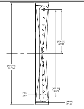
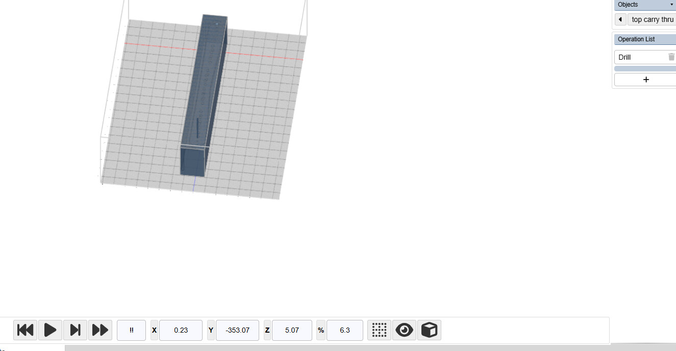
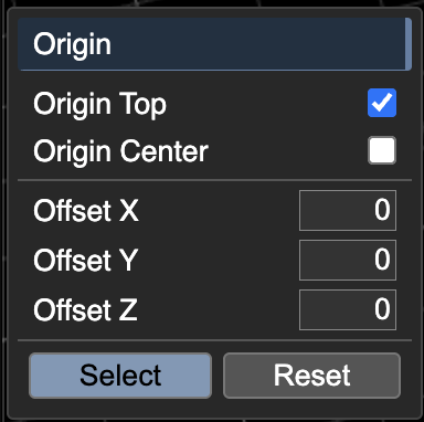
Shown screen shot of cad drawing with stock drawn in…screen shot of location of drill. Y 353 vs 352.4…X 0 vs .23 from the center of the stock with offsets of .289 X and 6.939 Y …off by 009 in x .023 in y (inches)
probably roundoff error is there a way to increase the significant calculated dimensions?
to clarify, you’re looking for more decimal points in the UI so it doesn’t get rounded?
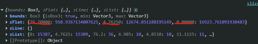
as an aside, what program produced this solid? we noticed that the vertex precision (especially in Z) is quite varied. KM sees these decimal point variations and decides that the flat surfaces are not actually flat. this is fixable.
Onshape and there was about 3 transitions to get it flat to the top plane so I can certainly understand that perhaps the issue is not with Kiri…And yes out to 12 places would be normal and there are buttons and settings for precision on Kiri which I am not sure if that is something I should be playing with…I will be able to dial in the machine from the location hole so it is not a big thing…Is something precisions users should be aware of weather or not it is poor cad or combination of roundoff. I see in preferences for Onshape angle and cord with numbers perhaps I need to change them.
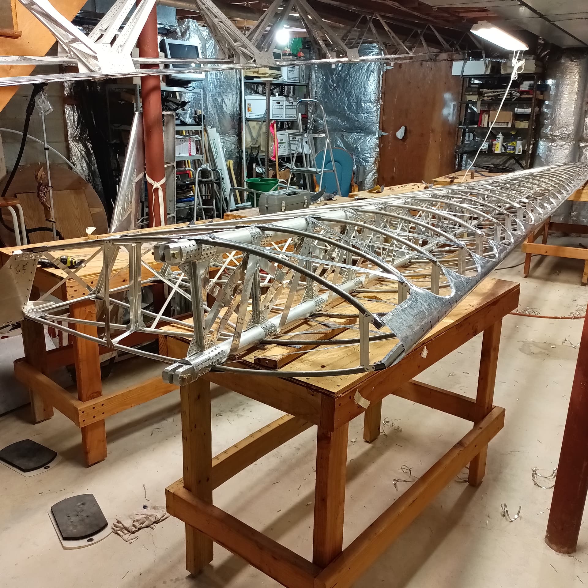
I will see if I can figure out a link that you can see it…however it is a public doc. and the title is:
The code currently finds the center of a hole by finding the average of all its edge points. This is a reliable method, and ideally maintains precision.
Regarding your main question, The precision in the animate screen is not what is being output in the gcode. the animate numbers are being rounded to a 2 fixed decimal points.
Feel free to export your generated gcode, and you can search for the points being output. This is the code as of now:
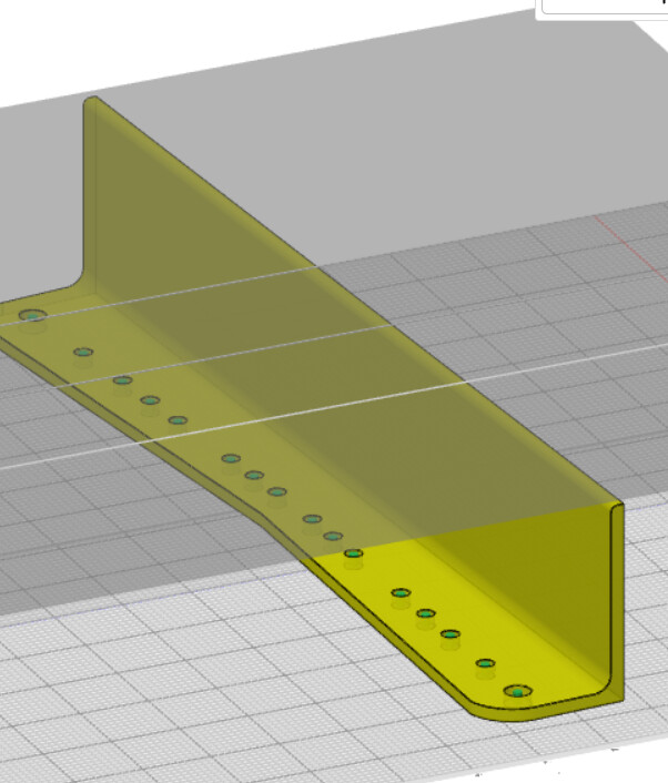
Regarding your CAD, It looks like you’re using a Part Studio almost like an Assembly, your part studio should be for making edits to the parts, and an assembly should be used for assembling and mating parts together. you can learn more from this forum post. you also seem to be using a lot of Move Face and Delete face operations in place of standard parametric features like Extrude. This approach may confuse Kiri:Moto, though I can’t say for sure. What I do know is for the base part you import, hole detection works great, and flat detection works perfectly.
There is a lot I have learned since I started to use this Cad… Link to LH Wing, Link to current redesign RH Wing …Thank you for your help and clarification I will check the Gcode
There is a way to get past the paywall…one does not have to be a supporting member …but you will have to somehow have a username and password to see the thread…if I remember how I will edit this post.