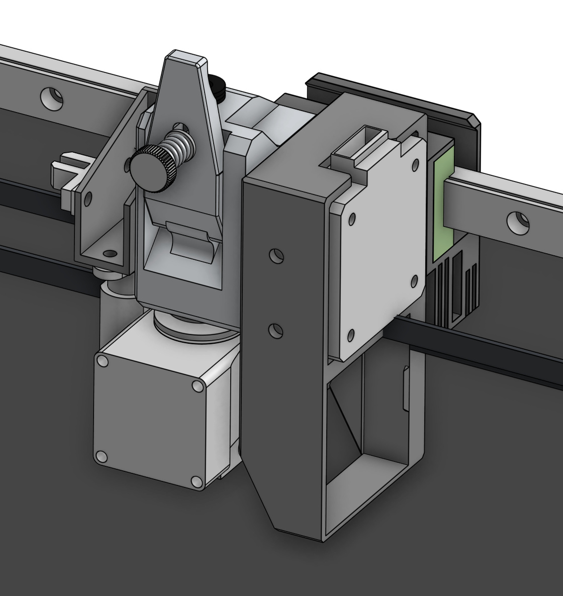
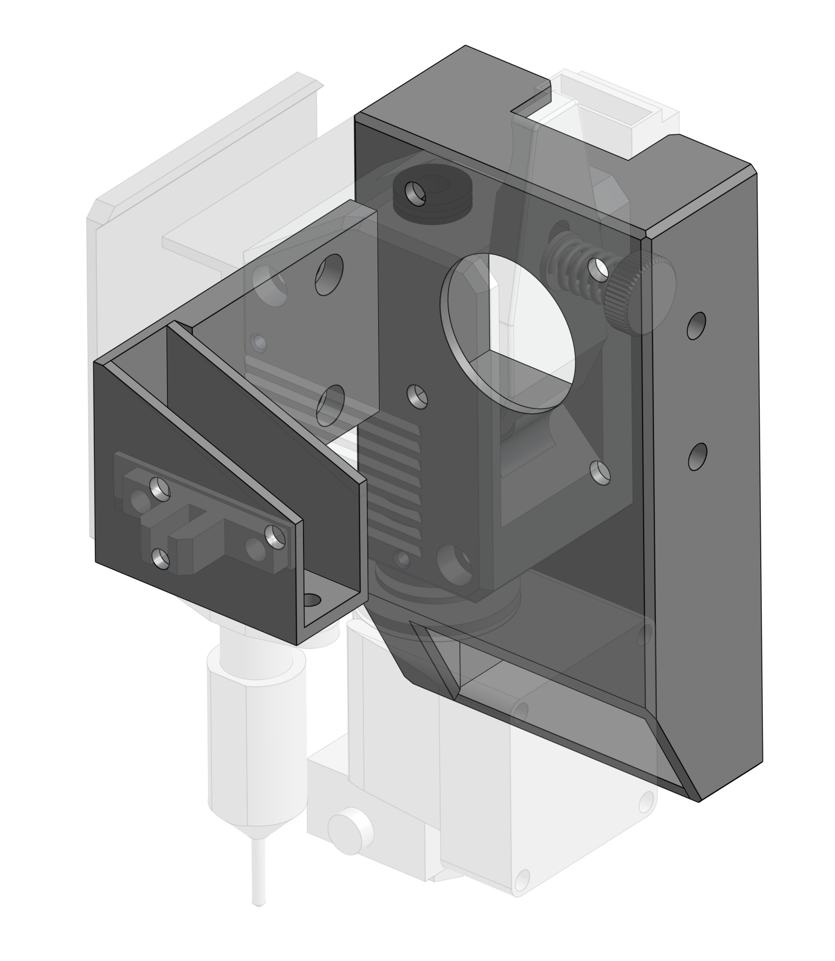
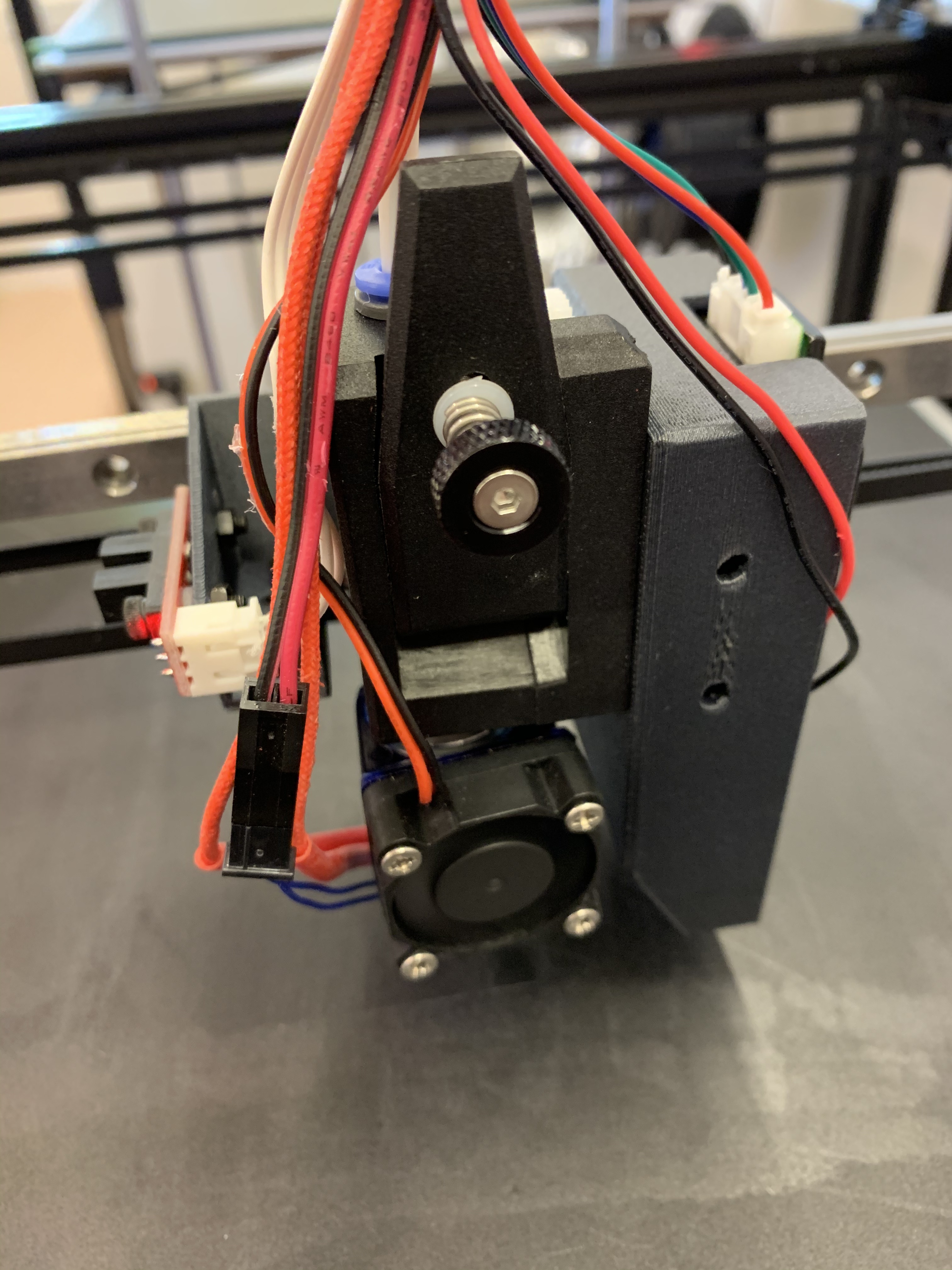
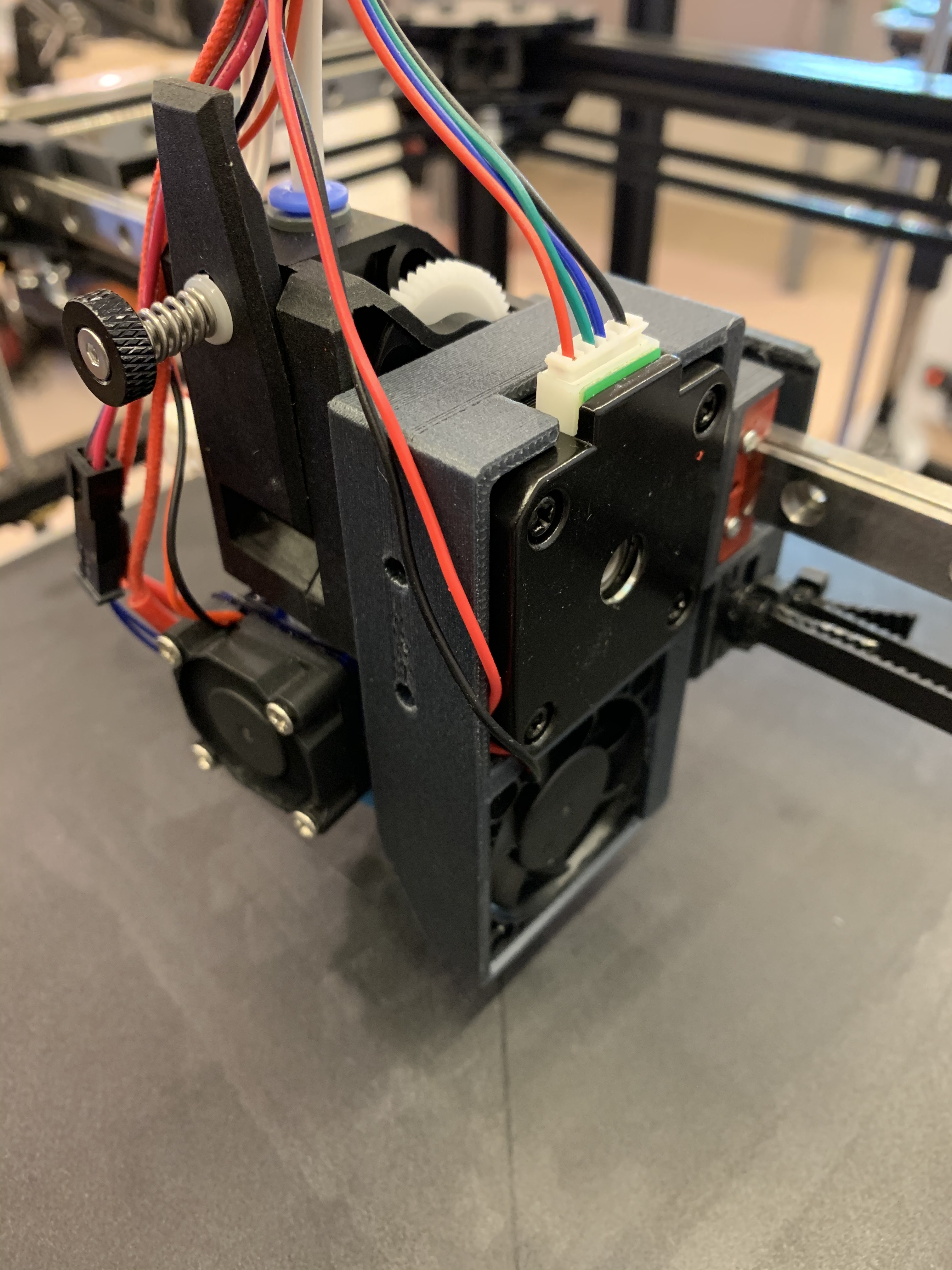
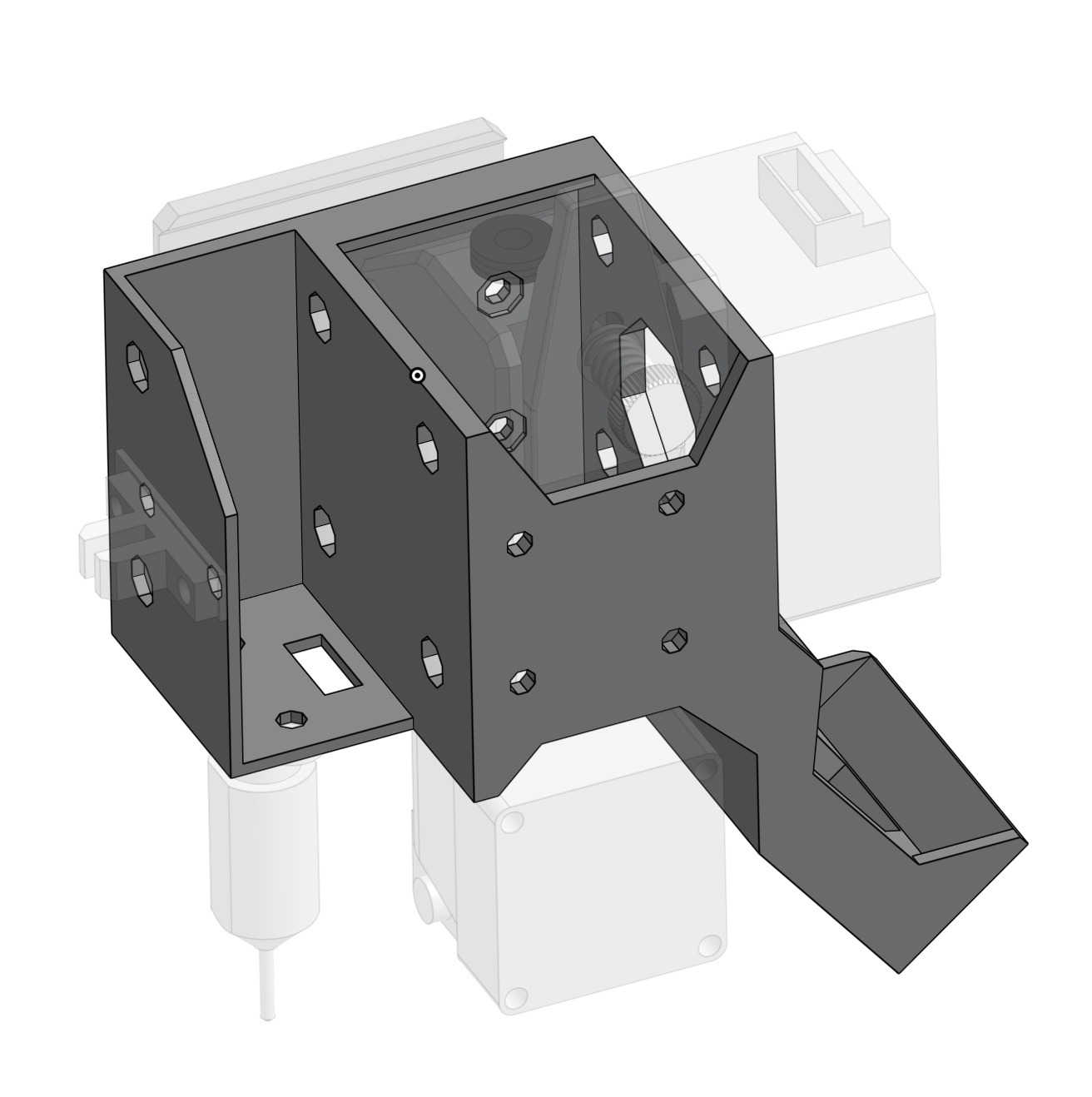
Using the two parts @jeffeb3 provided in a different thread, I made a modification to the GridBot V2 CAD model to mount them. The change out is relatively simple, but requires re-compiling the firmware to reverse the E axis direction. Also, the steps per mm on E goes from 100 to 400 since this is a geared drive.
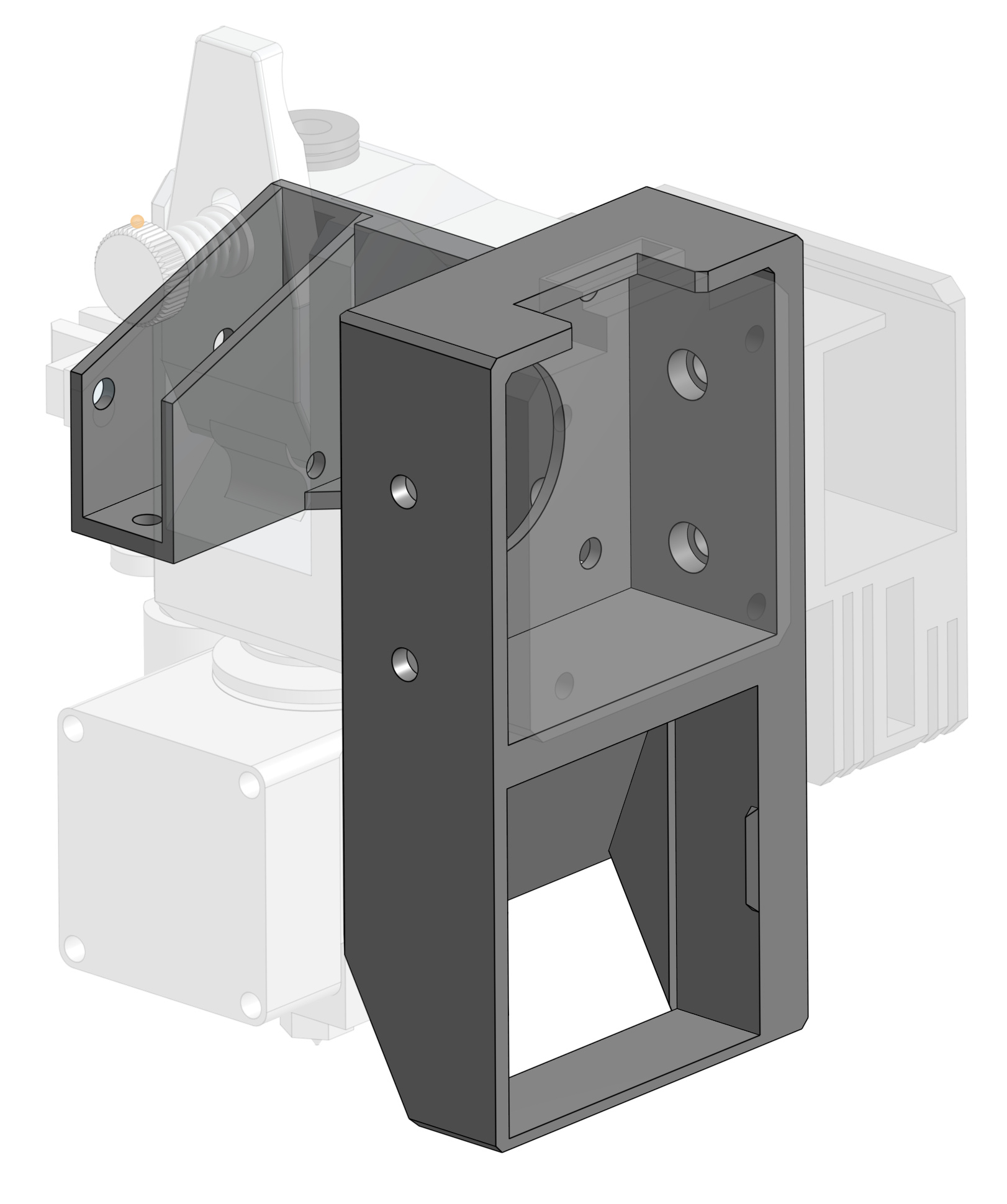
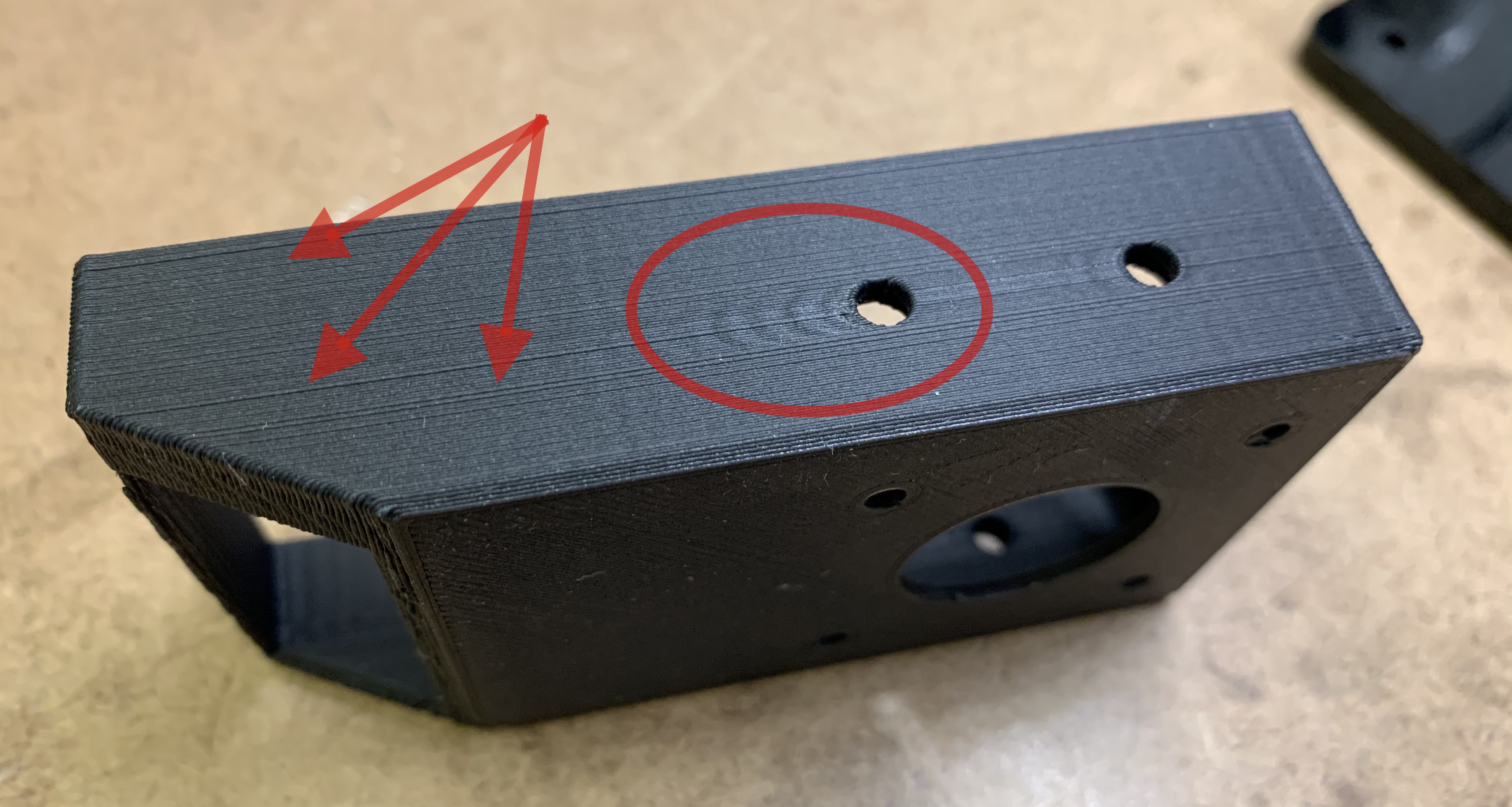
That looks nice. Interesting that it was broken into two mounts. I had trouble modifying the mount and keeping it printable. This seems easy to print and easy to modify.
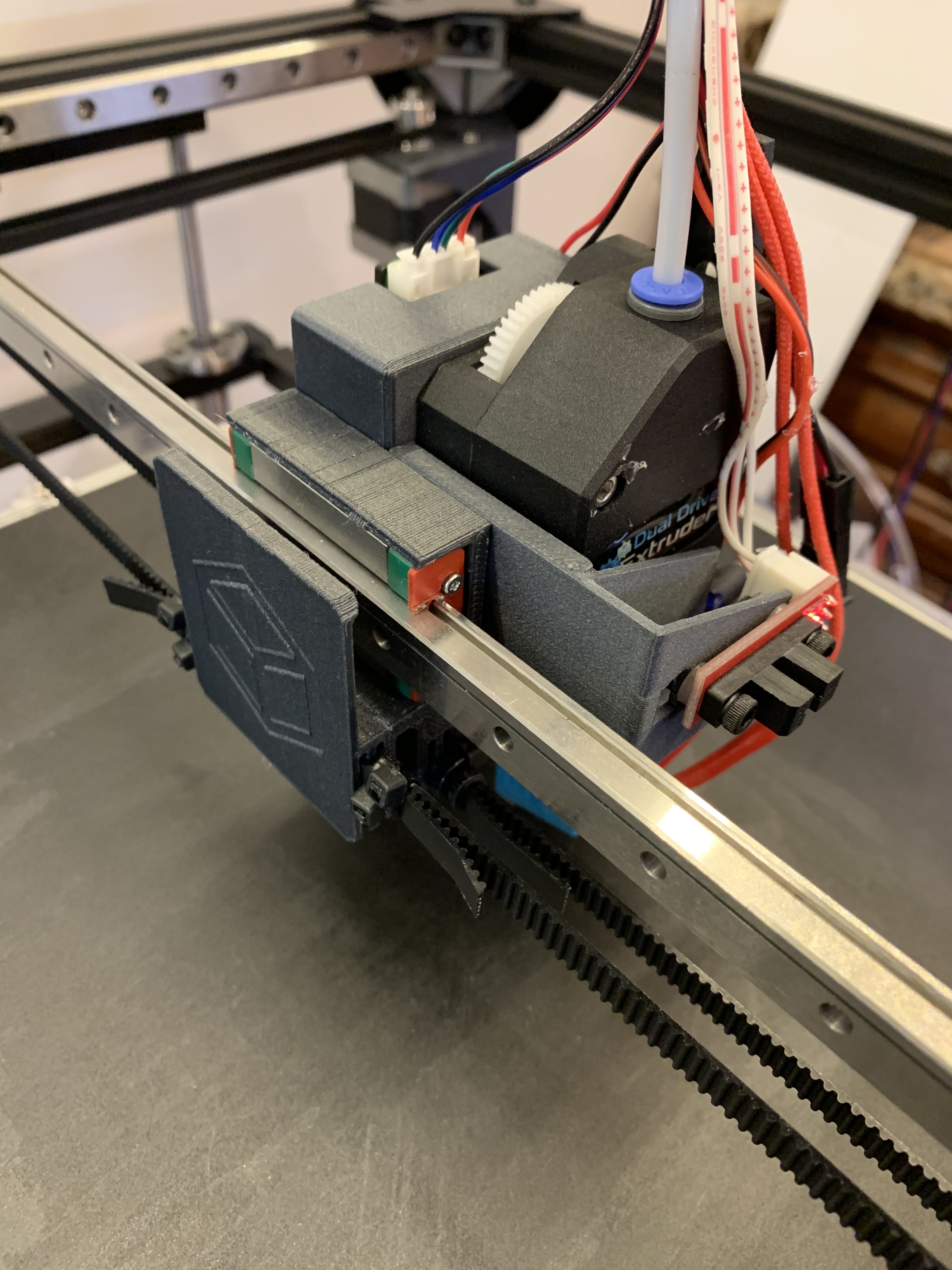
thanks. both pieces are easy to print. once mounted, it’s very rigid. I tried an SLA print, but that part was not as rigid as the carbon-filled PLA. the only thing I don’t like about this is that you lose about 1cm of printable area on the right side of the bed. fixing that shortcoming will require more extensive modifications [or you can move the bed off-center to the left :)].
I’m going to keep mine DD, but I wouldn’t try to push anyone into it. They each have pros/cons and they are both viable solutions. I don’t have Stewart’s version, so I can’t vouch for that either, but it looks good.
I would recommend you to do what you’d like. Ask questions if you have trouble. It’s a great platform for making your own way. That’s the best choice.
To add to this, the bowden extrusion setup has a few years of successful printing with the current GridBot design. I haven’t even tried a real print with the direct drive config yet. I am, at this very moment, fiddling with BLTouch setup and will likely make CAD changes based on that . It won’t likely affect printing, just how much of a hassle it is to setup the first time.
I’m seeing two things with the new setup that I’m going to attempt to fix. First, there is noticeable ringing on flat faces, especially at high speeds. This is to be expected when you greatly increase the mass of the head with a direct drive. Second, there appear to be some very slight layer registration problems. I’m not sure if this is because I turned off backlash compensation or because something in the belt setup is loose. I hope to figure that out tomorrow, too.
On the positive side, because the k-factor can run at or near zero with direct drive, the print head can move and accelerate faster around sharp features which reduces print times.
Spent a bunch of time on this today: printed new hardware, checked and tightened everything, tried an array of jerk, acceleration, and k-factor settings. Unable to materially improve the prints so far. The bowden prints are much cleaner. I suspect it could be the geared extruder drive. I seem to recall seeing something like that in the distant past with a similar drive system.
My next steps are to try a non-geared direct extruder mechanism. Will post results when I can.
I’m far from an expert. But one idea is bothering me. Perhaps it is the fact that only two screws are really holding the motor and extruder. Maybe it is able to rotate a small amount around the axis that goes through those two screws.